
TM 5-2420-230-24-2
B3.9 and B5.9 Series Engines
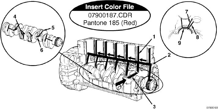
Flow Diagram, Lubricating Oil System
Section 7 - Lubricating Oil System - Group 07
Page 7-5
Lubrication for the Power Components
1. To valve train
6. Crankshaft, main journal
2. Main oil rifle
7. From main oil rifle
3. From oil cooler
8. To camshaft
4. Rod journal
9. To piston cooling nozzle.
5. To rod bearing
The main bearings and the valve train are lubricated by pressurized oil directly from the main oil rifle. The other power
components, connecting rods, pistons, and camshaft receive pressurized oil indirectly from the main oil rifle.
The drillings in the crankshaft supply oil to the connecting rod bearings. The oil is supplied to the camshaft journals
through drillings in the main bearing saddle. Smaller drillings in the main bearing saddle supply oil to the piston cooling
nozzles. The spray from the nozzles also provides lubrication for the piston pins.
The No. 1 main bearing saddle does not contain a piston cooling nozzle. Cylinder No. 1 receives the lubricating and
cooling spray from the nozzle located in the No. 2 bearing saddle. Cylinder No. 2 receives the spray from the No. 3
bearing saddle, etc.
Lubrication for the valve train is supplied through separate drillings in the cylinder block. The oil flows through the
drillings and across the oil transfer slot in the cylinder head gasket. From the transfer slot, the oil flows around the outside
diameter at the cylinder head capscrew, across a slot in the bottom of the rocker lever support, and up a vertical drilling
in the support. From these drillings, oil flows through drillings in the rocker lever shaft to lubricate the rocker levers.
Oil flows through a drilling in the rocker levers to fill a channel cast into the top of the levers. The oil from the channel
lubricates the valve stems, push tubes, and tappets.
L-1017