
TM 5-2420-230-24-2
Turbocharger Wastegate Actuator (010-050)
B3.9 and B5.9 Series Engines
Page 10-48
Section 10 - Air Intake System - Group 10
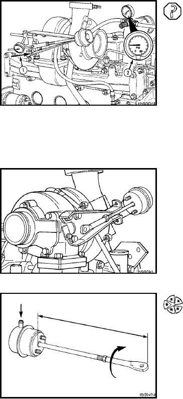
Test (010-050-012)
Functional Check
Attach a dial indicator as shown, so that its shaft is in line
with the wastegate actuator rod. Set the indicator to zero,
with no air pressure applied to the wastegate capsule.
Connect clean, regulated air pressure and a pressure gauge
to the capsule. Apply air pressure to make sure the
wastegate is functioning properly.
Air Pressure:
200 kPa
[29 psi]
The rod should move without any sticking or air leakage.
Rod:
0.33 to 1.27 mm
[0.013 to 0.050 in]
NOTE: No air should be heard leaking through a functional
wastegate capsule.
NOTE: A small amount of travel when air pressure is first
applied is normal; the tolerance is being removed from the
system.
Replace the actuator if no movement of the actuator rod
and lever is detected.
Install (010-050-026)
Install the adjusting link end onto the boost capsule act-
uator assembly. Adjust the rod to approximately the same
length as when removed.
L-1172