
TM 5-2420-230-24-2
Turbocharger Wastegate Valve Body (010-055)
B3.9 and B5.9 Series Engines
Page 10-50
Section 10 - Air Intake System - Group 10
CAUTION
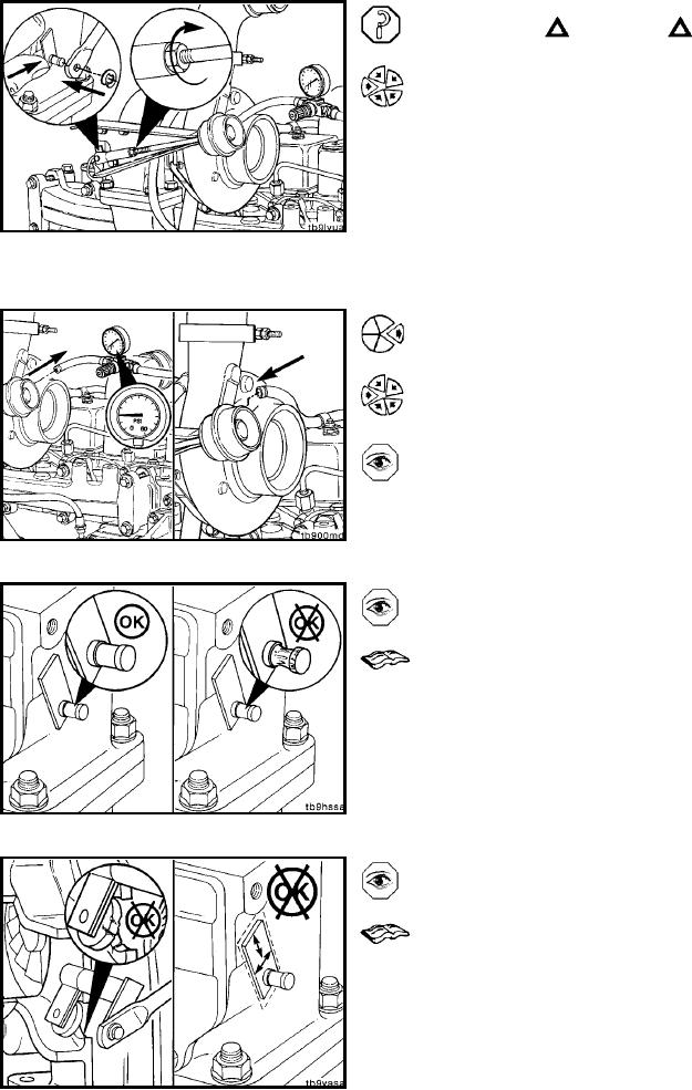
Do not pull, or push, or force alignment of the clevis
pin. Failure to do so can cause component damage.
Adjust the wastegate, if necessary, to achieve specified
travel.
Pull the wastegate lever to the foremost closed po-
sition (lever toward boost capsule).
Adjust the length of the clevis end of the control rod
to where the clevis pin hole aligns to the wastegate
lever.
Install the adjusting link and retaining clip.
After adjustment is completed, tighten actuator rod
jam nuts.
Disconnect regulated air pressure line from the boost cap-
sule.
Connect the turbocharger boost line to the boost capsule,
and secure the hose clamp.
If possible, a more accurate method of wastegate adjust-
ment is to check the manifold pressure at rated rpm ac-
cording to turbocharger boost pressure specifications.
Turbocharger Wastegate Valve Body
(010-055)
Inspect for Reuse (010-055-007)
Inspect the lever pin.
Replace the turbine housing assembly if worn excessively.
Refer to the Turbocharger Master Repair Manual, Bulletin
No. 3580555.
Inspect the valve and valve seat for cracks or erosion.
Replace the turbine housing assembly if worn excessively.
Refer to the Turbocharger Master Repair Manual, Bulletin
No. 3580555.
L-1174