
TM 5-2420-230-24-2
B3.9 and B5.9 Series Engines
Air Compressor Pin Bore Wear (012-010)
Section 12 - Compressed Air System - Group 12
Page 12-11
Air Compressor Pin Bore Wear
(012-010)
Initial Check (012-010-001)
WARNING
The unloader valve body is installed with spring ten-
sion. Use care when removing to prevent personal in-
jury. Always wear protective eyewear.
NOTE: This procedure applies to SS and ST models only.
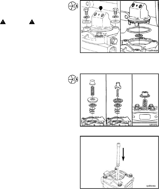
Hold the unloader valve body down, and remove the two
captive washer capscrews and the two plain washers.
Remove the unloader valve body.
Remove the o-ring seal.
Remove the rectangular ring seal.
Remove the unloader valve cap and the unloader valve
spring.
t OTE: Disassembly of the center unloader valve on Holset
N
wo-cylinder air compressors is similar to the single-cylinder
unloader valve.
Remove the intake valve seat and valve.
Remove the intake valve spring.
To avoid damage to the air compressor, do not allow any
debris to fall into the air compressor cylinder.
NOTE: Do not use a screwdriver. A screwdriver can gouge
the top of the piston.
Insert the small end of a 3/8-inch drive socket extension (6
to 10 inches long) through the exhaust valve seat onto the
top of the piston.
L-1215