
TM 5-2420-230-24-2
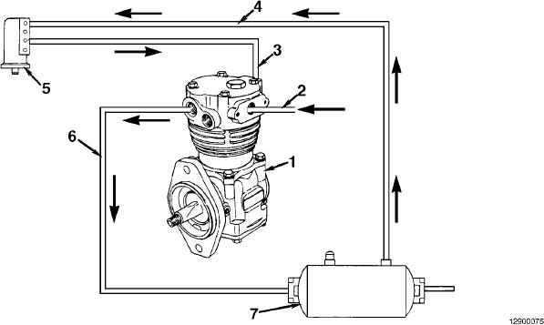
Flow Diagram, Compressed Air System
B3.9 and B5.9 Series Engines
Page 12-6
Section 12 - Compressed Air System - Group 12
1.
5. Governor
2.
Compressor intake
6. Discharge line
3.
Unloader line
7. Reservoir (wet tank).
4.
Reservior line
L-1210