
TM 5-2420-230-24-2
B3.9 and B5.9 Series Engines
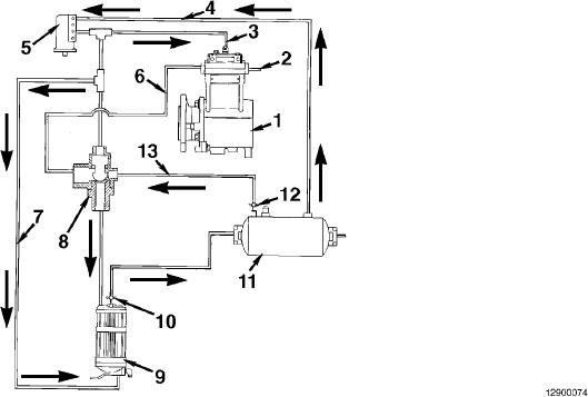
Flow Diagram, Compressed Air System
Section 12 - Compressed Air System - Group 12
Page 12-5
Flow Diagram, Compressed Air System
1.
8. Economy valve line
2.
Compressor intake
9. Air dryer
3.
E-Type unloader
10. Check valve (built into dryer)
4.
Reservoir line
11. Reservior (wet tank)
5.
Governor
12. Check valve
6.
Discharge line
13. Secondary pressure line.
7.
Splitter valve line
L-1209