
TM 5-2420-230-24-2
Starter Magnetic Switch (013-017)
B3.9 and B5.9 Series Engines
Page 13-24
Section 13 - Electrical Equipment - Group 13
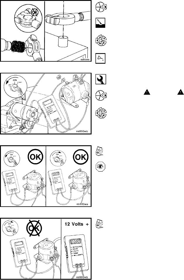
If the connections are corroded, remove the cables, and
use a battery brush to clean the cable and battery termi-
nals.
Install and tighten the battery cables.
Use dielectric grease to coat the battery terminals to pre-
vent corrosion.
Starter Magnetic Switch (013-017)
Initial Check (013-017-001)
WARNING
Be sure the starting motor switch is in the OFF position
to prevent electrical shock and personal injury.
Digital Multimeter, Part No. 3377161
Remove the cable connecting the magnetic switch to the
starting motor solenoid from the magnetic switch terminal.
Connect the leads of digital multimeter, Part No. 3377161,
or equivalent, to the two large switch terminals.
Set the multimeter to measure resistance (OHMS).
With the starting motor switch in the OFF position, the
multimeter must indicate resistance at infinity.
Turn the starting motor switch to the START position.
The multimeter must indicate zero or very little resistance.
If the multimeter indicates resistance at infinity with the
starting motor switch in the START position:
Turn the starting motor switch to the OFF position.
Set the multimeter scale to read DC voltage.
L-1282