
TM 5-2420-232-10
0002
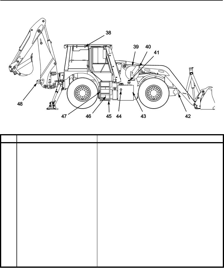
LOCATION AND DESCRIPTION OF MAJOR COMPONENTS CONTINUED
435-A0221
KEY
COMPONENT
DESCRIPTION
38
HVAC unit
Cleans, freshens, and cools the air entering the cab for a more com-
fortable working environment. Field houses a replaceable paper fil-
ter.
39
Auxiliary hose reel
Flexible hose holder for the auxiliary hydraulic powered hand tools.
40
Emergency shut-off button
Provides a means to disconnect the hydraulic power to the auxiliary
hand tool circuit quickly in an emergency.
41
Hydraulic tank filler cap
Provides a weatherproof and oil proof lockable cover for the hydrau-
lic fluid reservoir.
42
Front chassis tiedown and recovery points
Used to provide positive tiedown facility for transportation or for the
recovery of the machine.
43
Hydraulic fluid reservoir
Contains the machine s supply of hydraulic fluid.
44
Sight glass
Provides a visual means of checking the hydraulic reservoir fluid
level.
45
Steps
Provides access to cab.
46
Air tank drain tap
Provides a means of draining the water from the machine s air sys-
tem.
47
Air tanks
Hold the machine s supply of pressurized air for the brake system.
48
Tow pintle
Towing point for trailer.
0002-6