
TM 5-2420-232-10
0021
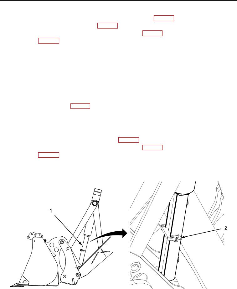
FRONT BUCKET CROWD CYLINDER STRUT INSTALLATION CONTINUED
2.
Raise the bucket sufficiently to give ground clearance to roll the bucket back (WP 0004).
3.
Roll the bucket back enough to install the strut (WP 0004).
4.
Ensure the parking brake is engaged and the transmission is in Neutral (WP 0004).
5.
Stop the engine (WP 0005).
6.
Remove the front bucket crowd cylinder travel strut (Figure 2, Item 1) from its stowage position on the spare wheel car-
rier.
7.
Place the strut (Figure 2, Item 1) around the cylinder piston rod as shown. Fix it in place with clamp and latch (Figure 2,
Item 2).
CAUTION
Roll the bucket carefully to prevent possible damage to the strut. Stop as soon as the weight of the
bucket is on the strut. Failure to follow this caution may result in damage to equipment.
8.
To prevent any chance of the strut (Figure 2, Item 1) becoming loose or creeping down, the bucket should be rolled for-
ward to trap the strut in position (WP 0004).
END OF TASK
FRONT BUCKET CROWD CYLINDER STRUT REMOVAL
0021
1.
Roll the bucket sufficiently to take the weight off the strut (WP 0004).
2.
Ensure the parking brake is engaged and the transmission is in Neutral (WP 0004).
3.
Stop the engine (WP 0005).
4.
Release the latch and clamp (Figure 2, Item 2), then remove the strut (Figure 2, Item 1).
5.
Secure the strut (Figure 2, Item 1) in its stowage position on the spare wheel carrier.
435-A1451
Figure 2. Front Bucket Crowd Cylinder Strut Location
021
END OF TASK
0021-3