
TM 5-2420-232-10
0020
TIRE INFLATION CONTINUED
3.
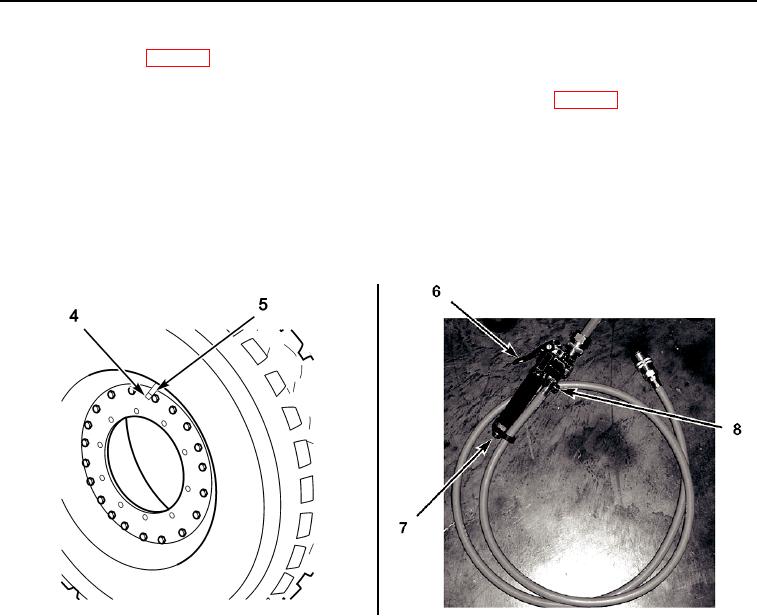
With engine running (WP 0005) and air pressure at normal operating pressure, remove dust cap (Figure 2, Item 4) from
tire valve (Figure 2, Item 5) and attach tire inflator assembly to tire valve.
4.
Operate the trailer air supply control valve in the cab to supply air to the trailer red line (WP 0004).
5.
Operate inflation lever (Figure 2, Item 6) on tire inflator assembly until the recommended tire pressure, 102 psi (703 kPa),
is indicated on pressure indicator rod (Figure 2, Item 7). Overpressure can be released by operating the deflation button
(Figure 2, Item 8).
6.
Once the correct pressure has been obtained, shut off air supply, remove tire inflator assembly from tire valve (Figure 2,
Item 5), and refit the dust cap (Figure 2, Item 4).
Remove tire inflator and hose assembly from the auxiliary air supply, replace the protective cover, and stow tire inflator
7.
assembly in the toolbox.
435-A0363
435-A0364
Figure 2. Tire Inflation
020
END OF TASK
END OF WORK PACKAGE
0020-3/(4 Blank)