TM 5-2420-232-10
0025
CONFIGURE MACHINE FOR HIGHWAY TRANSPORT
0025
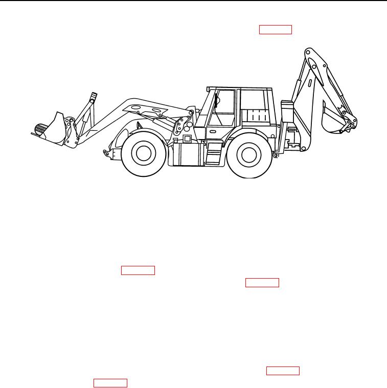
Load the spare wheel carrier assembly into the front bucket and secure as detailed in WP 0022.
435-A1311
Figure 1. Load Spare Wheel Carrier
025
END OF TASK
LOADING MACHINE ON TRAILER
0025
NOTE
Ensure wheels of trailer are chocked.
1.
Start engine and allow to warm up (WP 0005).
2.
Lower the suspension to the Transportation/Limp-home mode as detailed in WP 0004.
NOTE
If the crest angle to be negotiated when loading the HMEE-I onto the trailer is greater that 19
degrees, then it will be necessary to raise the loader arms as the machine is being loaded to obtain
the necessary clearance.
3.
Raise the front loader arms to the self-deployment position, but do not install the support struts.
4.
Angle the front bucket to the self-deployment position, but do not fit the support.
5.
Position the backhoe in the travel position. Engage the boom lock and swing lock (WP 0005).
6.
Ensure the rear stabilizers (WP 0004) are fully raised.
0025-2

