
TM 5-2420-232-10
0041
SWEEPER CONTROLS CONTINUED
Slewing of the Sweeper Carriage
00041
The second (auxiliary) lever operates the rotation and the slewing of the sweeper carriage. The lever has an auxiliary switch
built into the lever knob. Without the switch being operated, the lever acts as described in Engaging the Sweeper. When the
button is depressed, it changes the rotation operation to the slewing operation described below.
The main and auxiliary levers can be operated at the same time to produce combined sweeper actions as previously described.
WARNING
Accidents can be caused by working in poor visibility. Keep windows clean and use your lights to
improve visibility. Do not operate the machine if you cannot see properly. Failure to follow this
warning may result in injury or death to personnel.
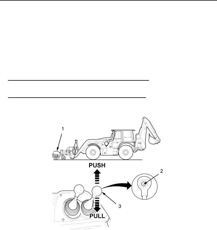
To Slew the Sweeper Carriage to the RIGHT (As Seen from Operator's Seat). To slew the sweeper carriage (Figure
1.
7, Item 1) to the right, depress and hold the auxiliary system button (Figure 7, Item 2) in the auxiliary control lever (Figure
7, Item 3) and pull the lever backwards.
2.
To Slew the Sweeper Carriage to the LEFT (As Seen from Operator's Seat). To slew the sweeper carriage (Figure 7,
Item 1) to the left, depress and hold the auxiliary system button (Figure 7, Item 2) in the auxiliary control lever (Figure 7,
Item 3) and push the lever forwards.
435-A1406
Figure 7. Slewing Sweeper
041
0041-8