
TM 5-3805-280-10
Maintenance--Every 1000 Hours
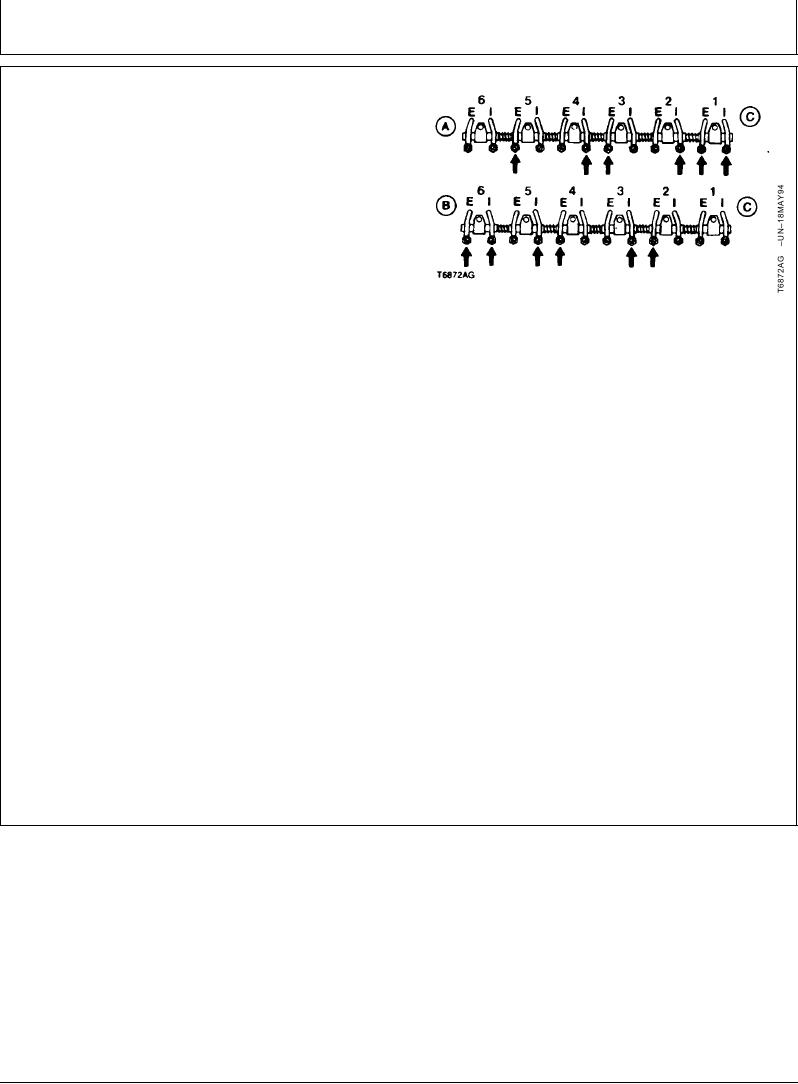
FIRING ORDER 6--CYLINDER ENGINE:
NOTE: Firing order is 1-5-3-6-2-4.
1. Adjust No. 1, 3, and 5 exhaust valves and No. 1, 2,
and 4 intake valves.
Exhaust Valves (E)--Specification
Clearance ................................................................... 0.46 mm (0.018 in.)
Intake Valves (I)--Specification
Clearance ................................................................... 0.36 mm (0.014 in.)
A--No. 1 TDC Compression Stroke
2. Rotate engine 360 and repeat step 1 for the remaining
B--No. 1 TDC Exhaust Stroke
C--Fan End of Engine
intake and exhaust valves.
3. Tighten jam nut to 27 Nm (20 lb-ft).
4. Clean cylinder head and rocker arm cover mating
surfaces.
5. Install rocker arm cover gasket. Do not use sealant on
the gasket.
6. Install rocker arm cover. Tighten screws to 35 Nm (26
lb-ft). Do not over tighten cap screws.
7. Remove turning tool and timing pin.
8. Install parts. Center muffler to turbocharger inlet tube
before fastening muffler into place.
CED,OUOE042,28 1908MAR991/1
16-5