
TM 5-3805-280-24-1
Torque Values
9000
SERVICE RECOMMENDATIONS FOR INCH SERIES FOUR BOLT FLANGE FITTINGS
03
10
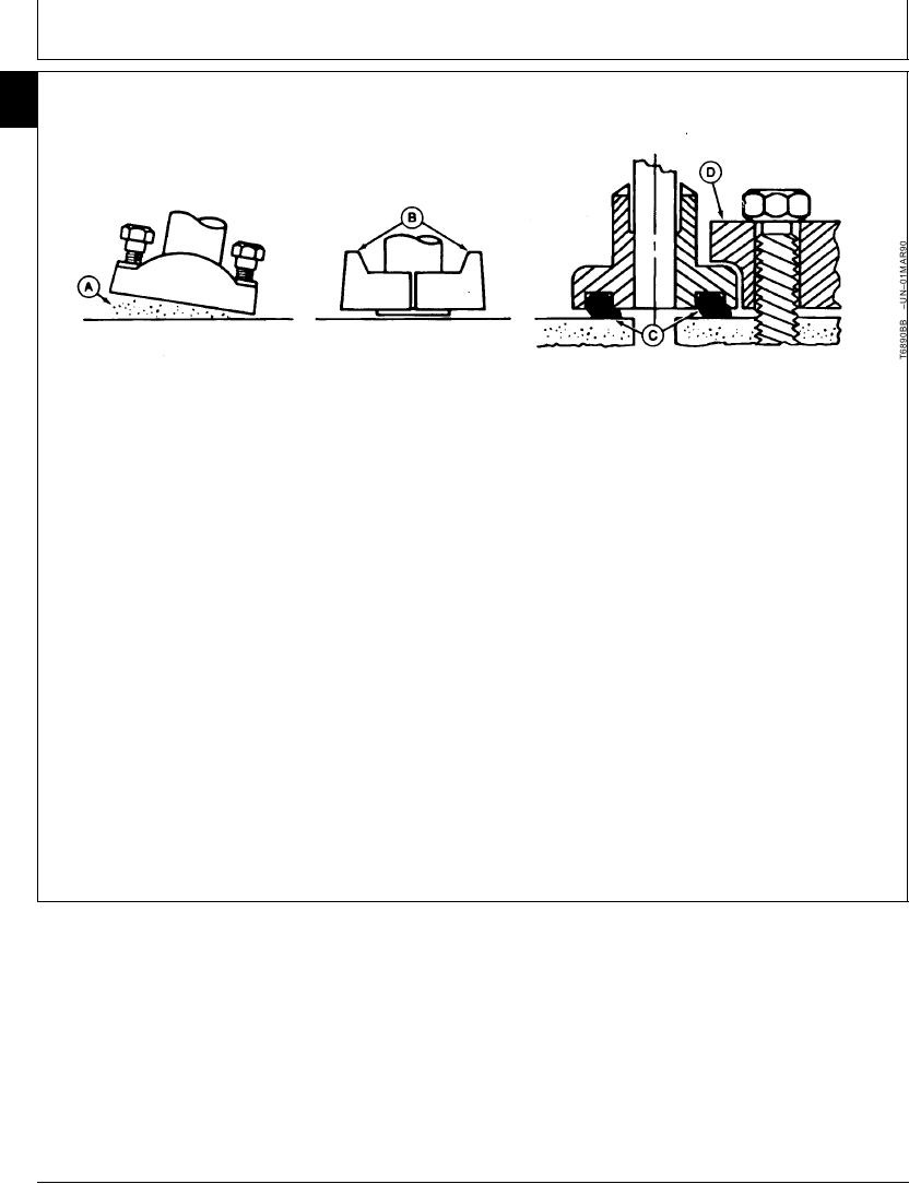
A--Sealing Surface
B--Split Flange
C--Pinched O-Ring
D--Single Piece Flange
must be centrally located on port. Hand tighten cap
1. Clean sealing surfaces (A). Inspect. Scratches
screws to hold flange in place. Do not pinch O-ring.
cause leaks. Roughness causes seal wear.
Out-of-flat causes seal extrusion. If defects cannot
5. Tighten one cap screw, then tighten the diagonally
be polished out, replace component.
opposite cap screw. Tighten two remaining cap
screws. Tighten all cap screws as specified in the
2. Install O-ring (and backup washer if required) into
chart below.
groove using petroleum jelly to hold it in place.
DO NOT use air wrenches. DO NOT tighten one
3. Split flange: Loosely assemble split flange (B)
cap screw fully before tightening the others. DO
halves. Make sure split is centrally located and
NOT over tighten.
perpendicular to port. Hand tighten cap screws to
hold parts in place. Do not pinch O-ring (C).
4. Single piece flange (D): Place hydraulic line in
center of flange and install cap screws. Flange
Continued on next page
04T,90,K174
1901AUG941/2
1-29