
TM 5-3805-280-24-1
Sub-System Diagnostics
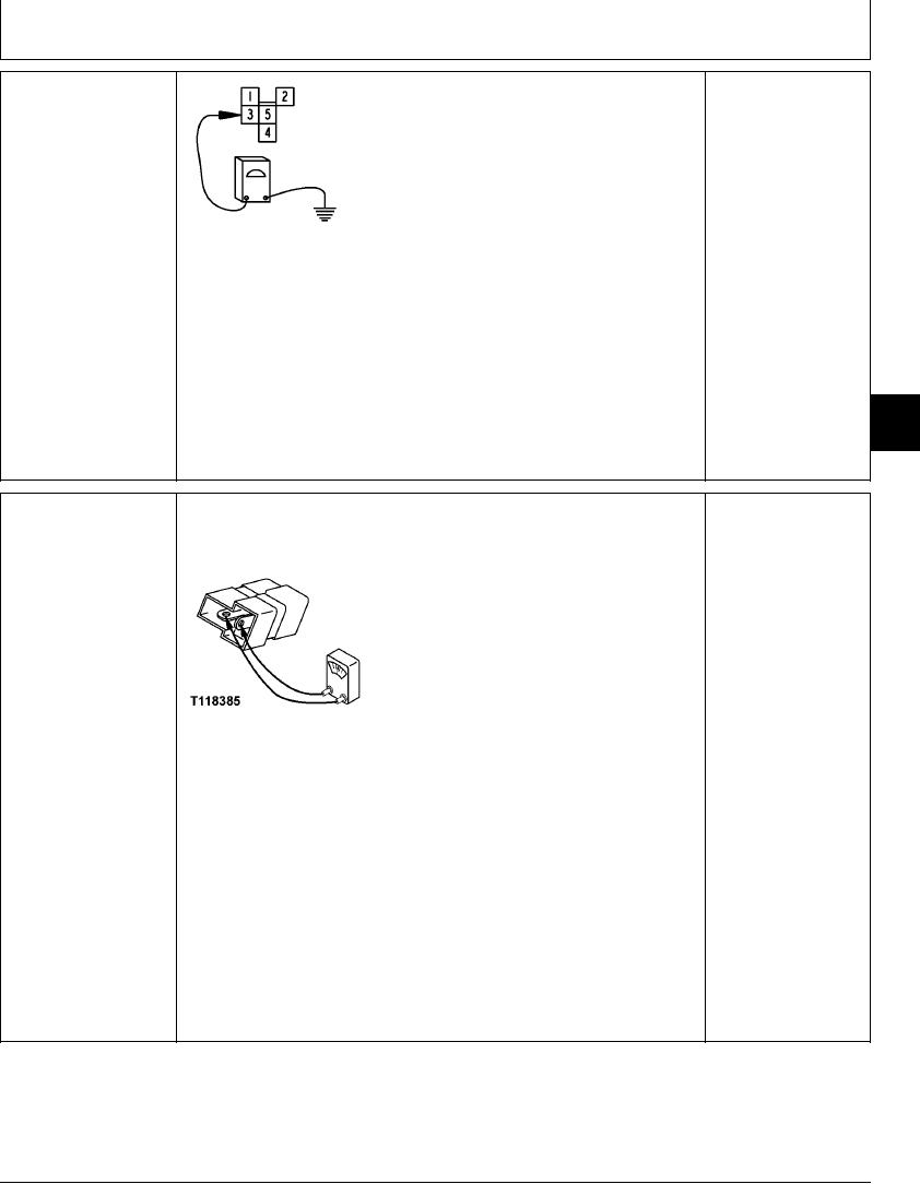
YES: Harness is OK.
1--24-Volt Terminal
2--Ground Terminal
3--Relay Common 5 Volts To D9
NO: Harness or engine
4--Relay Normally Closed
and pump controller has
5--Relay Normally Open To Ground
failed. Repair or replace.
ground.
T102860 UN12AUG96
Turn key switch ON.
Does voltmeter read 5 volts.
9015
15
91
2/2
NOTE: A diode can fail in two modes, either shorted or open. Continuity will be
PROPEL AUTO IDLE
YES: If continuity is
measured in one direction only in a serviceable diode. Use "diode checking mode" on
RELAY ISOLATION
measured in both checks,
meter when checking continuity.
DIODE (V4) CHECK
diode has failed in a
shorted mode. Replace.
NO: If continuity is NOT
measured in either check,
diode has failed in an
open mode. Replace.
NO: If continuity is
measured in one check
and not the other, diode
T118385 UN21NOV98
is OK.
Remove diode from connector.
Connect an ohmmeter to diode terminals.
Is continuity measured?
Reverse ohmmeter probes.
Is continuity measured?
1/1
4-156