
TM 5-3805-280-24-1
Sub-System Diagnostics
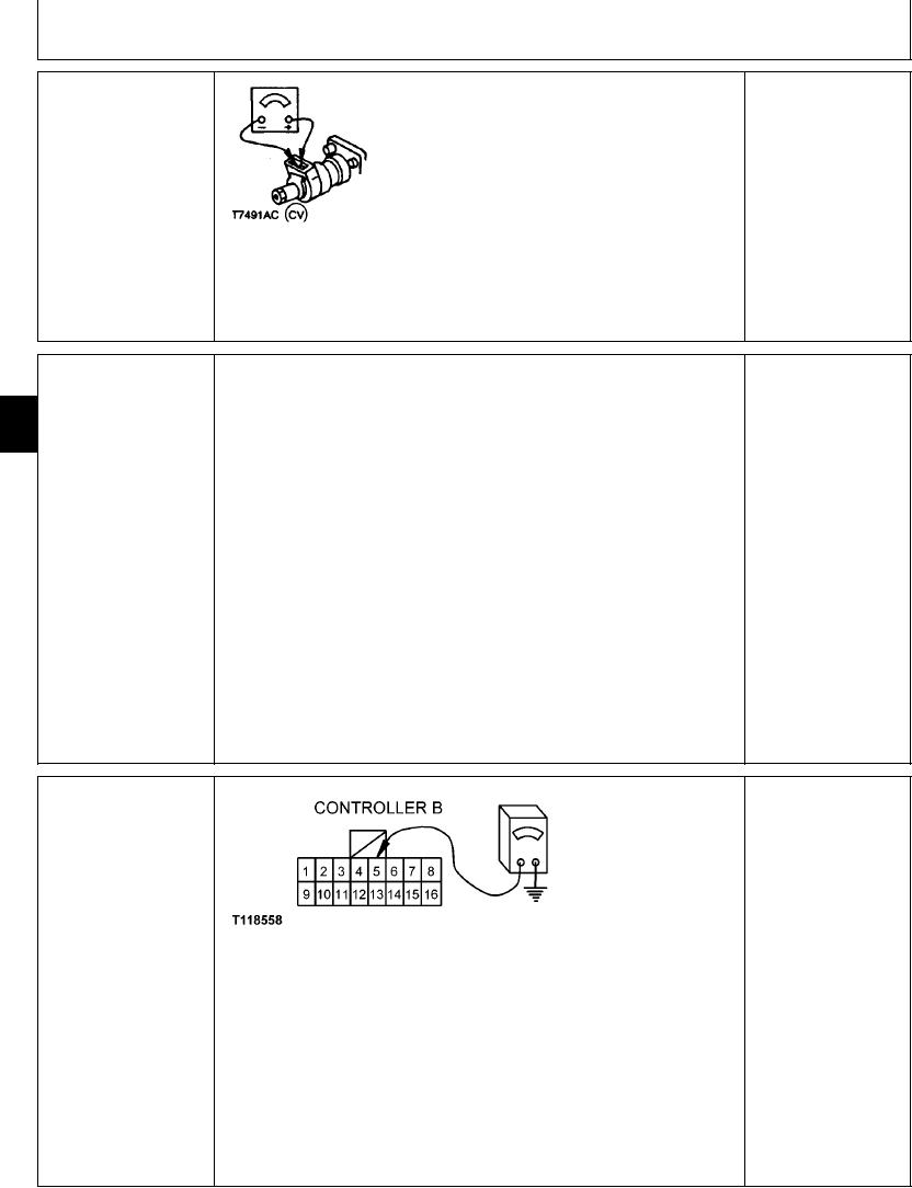
SPEED SENSE
Turn key switch OFF.
YES: Solenoid is OK. Go
PROPORTIONAL
to next check.
SOLENOID (Y8) CHECK
Remove wire clip from bottom of solenoid harness
connector.
NO: Solenoid has failed.
Replace.
Disconnect harness from solenoid.
Connect ohmmeter to solenoid terminals.
T7491AC
UN08APR91
Does ohmmeter read approximately 24 ohms?
1/1
YES: Harness and engine
Turn key switch OFF.
SPEED SENSE
and pump controller are
PROPORTIONAL
9015
OK.
SOLENOID (Y8)
Install proportional solenoid test harness JT07352 in series with wiring harness and
15
HARNESS CHECK
sense solenoid.
94
NO: Harness or engine
and pump controller has
Connect voltmeter to test harness jacks.
failed. Repair or replace.
Start engine, set auto idle mode to OFF, and set engine idle to medium speed so that
voltmeter reads approximately 5.5 volts (RPM dial set at first bar after mid range).
Bottom arm in to load engine.
Does voltmeter read approximately 7 volts with arm bottomed in?
1/1
LEARNING SWITCH
YES: Switch and harness
(S16) CHECK
are OK.
NO: Switch or harness
has failed. Check and
repair or replace.
T118558 1921NOV98
Turn key switch OFF.
Disconnect 16-pin connector B from engine and pump controller.
Turn switch to ON.
Measure continuity from pins 5 of connector B to ground.
Is continuity measured?
1/1
4-159