
TM 5-3805-280-24-1
Tests
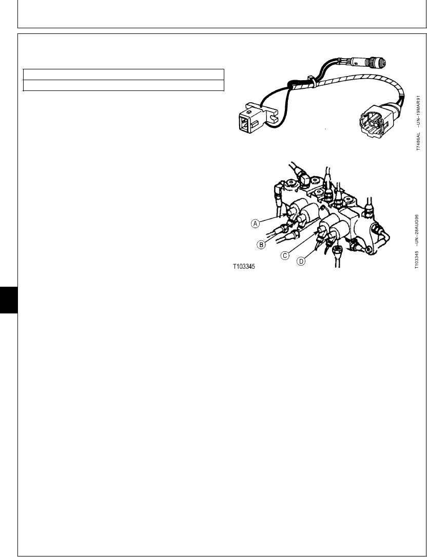
SPEED SENSING SOLENOID VALVE (SD)
HARNESS TEST
ESSENTIAL TOOLS
JT07062 Test Harness
The purpose of test is to check continuity in wiring
harness to the speed sensing solenoid valve (B) coil and
there is a electrical signal from engine and pump
controller.
NOTE: Pressure reading shown on the laptop computer
for "11 Speed sense control pressure" is a
calculated pressure from the electrical signal in
the engine and pump controller. When all
functions are in neutral, a typical reading of 532.8
psi is displayed at slow idle and 0 psi is displayed
at fast idle. Run the engine at approximately 1700
rpm so the reading is less than 100 psi. Then
actuate arm in to bottom the function. The
pressure reading will increase momentarily and
then return to its original reading. The readings
indicates that the engine speed sensor is OK and
a electrical signal is generated. (For circuit
operation, see Engine Speed Sensing Control
Circuit Operation in Group 9025-05.)
A--Arm Regenerative Solenoid Valve (SC)
9025
B--Speed Sensing Solenoid Valve (SD)
IMPORTANT: Disconnecting electrical connectors
25
C--Propel Speed Change Solenoid (SI)
42
D--Power Boost Solenoid Valve (SG)
while engine is running or with key
switch on can damage engine and
pump controller or other electrical
components.
1. Stop engine. Turn key switch to OFF.
2. Remove wire clip. Wiggle connector half and pull apart;
do not pull on wiring leads.
3. Install test harness in series with wiring harness and
speed sensing solenoid valve (B).
4. Turn key switch to ON but do not start engine.
Indicator light must come ON indicating there is
continuity in the wiring harness and there is a signal
from engine and pump controller.
Continued on next page
TX,25,GG2221
1901JUN981/2
6-173