
TM 5-3805-280-24-1
Tests
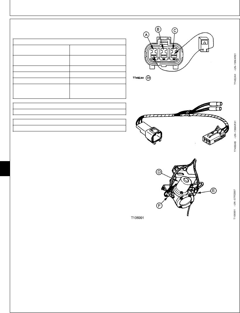
ENGINE CONTROL SENSOR (EC SENSOR)
HARNESS TEST
SPECIFICATIONS
2000 400 ohms between
Engine Control (EC) Sensor
ground and power terminals
Fast Idle in Standard Mode
3.3--3.7 volts typical
Voltage
E (Economy) Mode Voltage
3.0--3.3 volts typical
Auto-Idle Mode Voltage
2.7--2.9 volts typical
Slow Idle Voltage
2.5--2.7 volts typical
HP (High Power) Mode With Arm
Fast idle in standard mode
In Function Over Relief Voltage
voltage plus 0.1 volt or more
typical
ESSENTIAL TOOLS
JT07066 Test Harness
SERVICE EQUIPMENT AND TOOLS
JT07306 Analog/Digital Multimeter
The purpose of test is to check continuity in engine control
sensor (EC sensor) wiring harness and there is a signal
from the engine and pump controller (EPC).
NOTE: The reading displayed on the laptop computer for
9025
"2 EC angle" is the feedback signal from the
25
engine control sensor to the engine and pump
48
controller. See the specification chart above for
typical readings for fast idle, slow idle, E mode,
HP mode, and auto-idle mode. The readings can
vary from machine to machine. What to look for is
that the readings change when the engine rpm
dial is turned, and the E mode, HP mode, or
auto-idle mode is actuated. The readings indicates
engine control sensor is OK. (For circuit operation,
see Engine Speed Control System Operation in
Group 9010-05.)
A--Ground Terminal
B--Signal Terminal
IMPORTANT: Disconnecting electrical connectors
C--Power Terminal
while engine is running or with key
D--Engine Control Motor
switch on can damage engine and
E--Engine Control Sensor Wiring Harness
pump controller or other electrical
F--Engine Control Motor Wiring Harness
components.
1. Stop engine. Turn key switch to OFF.
Continued on next page
TX,9025,GG2710
1913AUG981/3
6-179