
TM 5-3805-280-24-1
Tests
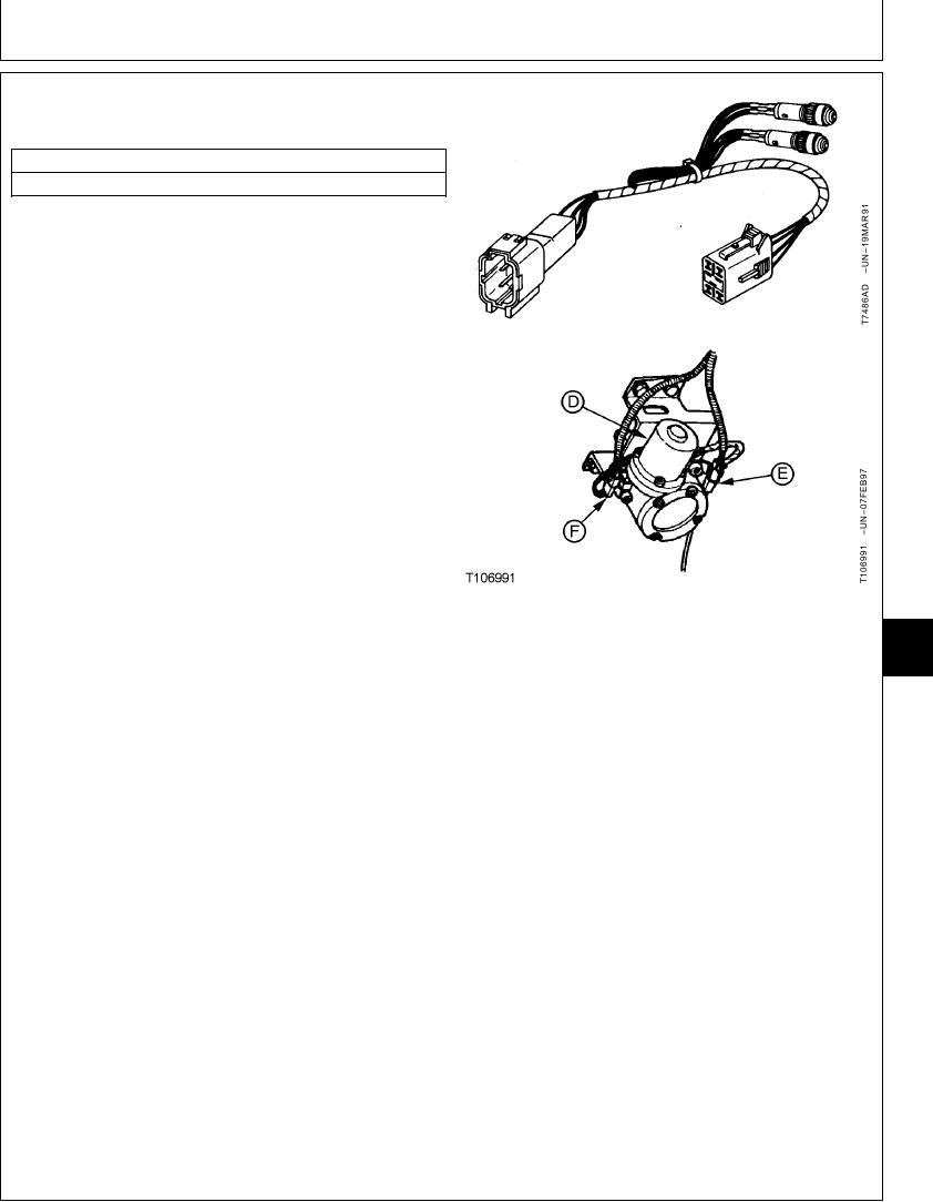
ENGINE CONTROL MOTOR (EC MOTOR)
HARNESS TESTS
ESSENTIAL TOOLS
JT07065 Test Harness
The purpose of test is to check continuity of EC motor
wiring harness (F) and there is a signal from engine and
pump controller (EPC).
NOTE: The laptop computer with excavator diagnostics
program can be used to check the electrical signal
from the engine and pump controller to the engine
control motor. Select "15 EC motor position" from
Monitor Data Items. Typical readings are 72--76
steps at slow idle to 525--550 steps at fast idle.
The readings can vary from machine to machine.
What to look for is that the readings change when
the engine rpm dial is turned, and the E mode,
HP mode, or auto-idle mode is actuated.
IMPORTANT: Disconnecting electrical connectors
while engine is running or with key
switch on can damage engine and
pump controller or other electrical
components.
D--Engine Control Motor
9025
E--Engine Control Sensor Wiring Harness
1. Stop engine. Turn key switch to OFF.
25
F--Engine Control Motor Wiring Harness
51
IMPORTANT: Retainer tab on male half of wiring
harness connector halves must be
pushed down before pulling halves
apart. Never pull on wiring leads.
2. Push retainer tab down then pull connector halves
apart.
3. Install test harness in series with the engine control
motor wiring harness (F).
4. Turn key switch to ON.
5. While observing test indicator lights,
a. Turn engine rpm dial from slow idle to fast idle,
Continued on next page
TX,25,GG2223
1913AUG981/2
6-182