TM 5-3805-280-24-1
Tests
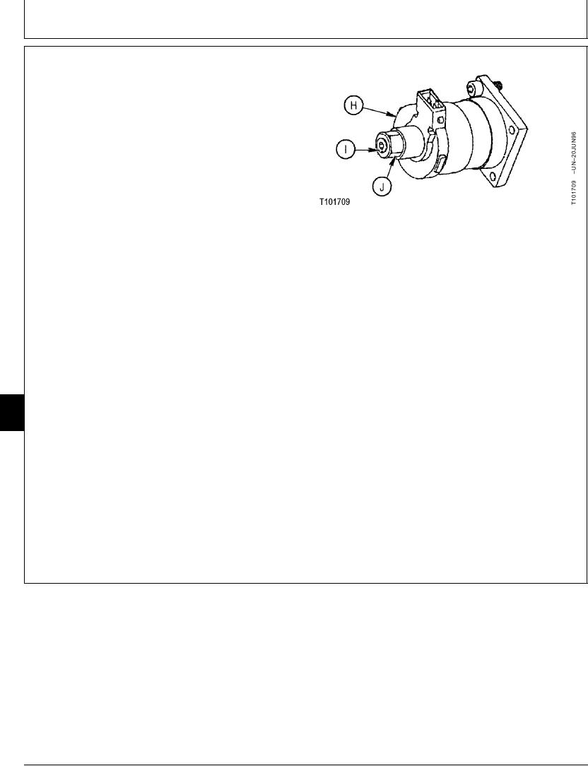
8. Adjust the solenoid valve (H) as needed. Turn
adjusting screw (I) IN to increase pressure setting; turn
adjusting screw out to decrease pressure setting. Hold
screw and tighten nut (J).
Make a mark on the end of adjusting screw for the
original position of screw. Do not mark on threads of
screw.
IMPORTANT: Turning adjusting screw out too far may
cause oil leakage because the O-ring
has come off its seat. The length from
end of adjusting screw to nut must not
H--Solenoid Valve
exceed 4 mm (0.157 in.).
I--Adjusting Screw
J--Nut
Loosen nut just enough so adjusting screw can be
turned. Turn adjusting screw in to increase pressure;
turn adjusting screw out to decrease pressure.
Proportional Solenoid Valve--Specification
Pressure ........................................................... 98 kPa (0.98 bar) (14 psi)
approximate change per 1/4 turn
of adjusting screw
End of Adjusting Screw to Nut Must Not Exceed--Specification
Length.............................................................................. 4 mm (0.157 in.)
9025
25
Hold adjusting screw and then tighten nut.
88
Adjusting Screw-to-Housing Nut--Specification
Torque ........................................................................... 8.8 Nm (78 lb-in.)
Check the pressure again.
TX,9025,GG2121
1921MAY986/6
6-219

