
TM 5-3805-280-24-2
Cylinder Head and Valves
MEASURE VALVE LIFT
05
13
IMPORTANT: For a more accurate measurement,
measure valve lift at 0.00 mm (in.)
rocker arm-to-valve tip clearance and
with engine COLD.
NOTE: Measuring valve lift provides an indication of wear
on camshaft lobes and cam followers or push
rods.
1. Remove rocker arm cover.
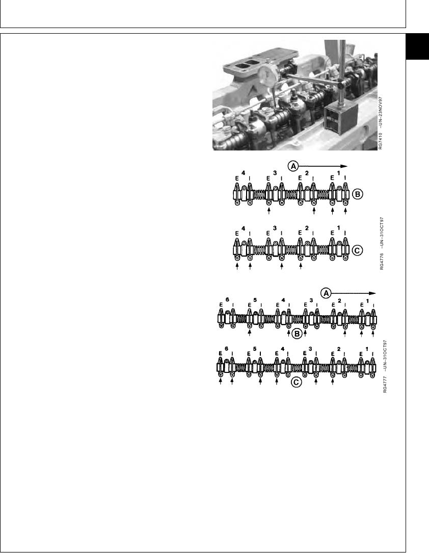
2. Set No. 1 piston at TDC compression stroke and install
JDE81-4 Timing Pin in flywheel.
3. Set rocker arm-to-valve tip clearance to 0.00 mm (in.)
for:
No. 1 and 3 exhaust and No. 1 and 2 intake valves
on 4-cylinder engines.
No. 1, 3, and 5 exhaust and No. 1, 2, and 4 intake
valves on 6-cylinder engines.
4. Place dial indicator tip on top of valve spring cap
(retainer) or rotator. Preload indicator tip and set dial at
4-Cylinder Engine
0.0 mm (in.).
5. Remove timing pin from flywheel and manually rotate
engine one full revolution (360) in running direction
using appropriate flywheel turning tool.
6. Observe dial indicator reading as valve is moved to full
open. Record maximum reading and compare with
specifications given below.
Intake Valves--Specification
Lift .......................................................... 11.77--12.21 mm (0.463--0.481
in.)
6-Cylinder Engine
Wear Limit ................................................................ 11.34 mm (0.447 in.)
A--Front of Engine
B--No. 1 Piston TDC Compression
Exhaust Valves--Specification
C--No. 4 Piston or No. 6 Piston TDC
Compression
Lift .......................................................... 11.51--11.94 mm (0.453--0.470
E--Exhaust Valve
in.)
I--Intake Valve
Wear Limit ................................................................ 11.08 mm (0.436 in.)
Continued on next page
RG,05,DT7374 1911NOV971/2
13-71