
TM 5-3805-280-24-2
Air Intake and Exhaust System
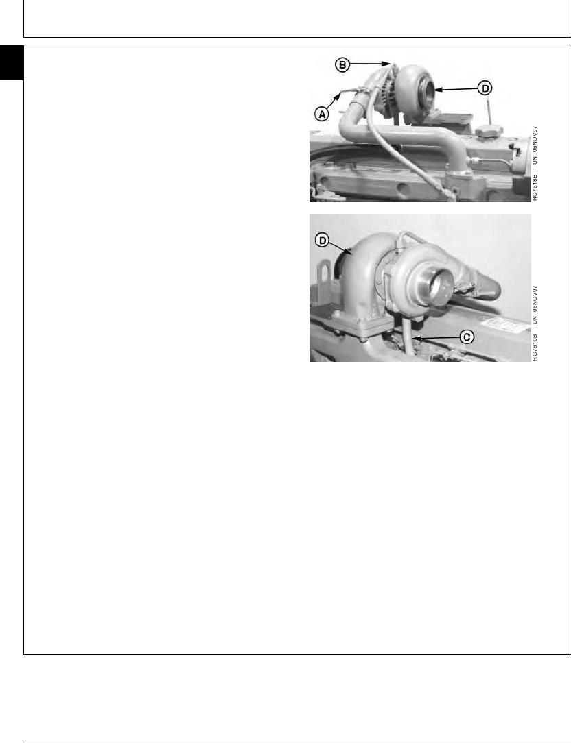
INSTALL TURBOCHARGER
30
18
IMPORTANT: If turbocharger failed because of foreign
material entering the air intake system,
be sure to examine the system and
clean as required to prevent a repeat
failure.
If not done previously, prime (prelube) the turbocharger
rotating assembly prior to mounting turbocharger on
engine. Prelube center housing with clean engine oil
through the oil drain hole. Turn rotating assembly by hand
to lubricate bearings.
1. Position turbocharger (D) and new stainless steel
gasket onto exhaust manifold. Tighten stud nuts to
specifications.
Turbocharger-to-Exhaust Manifold Nuts--Specification
Torque ............................................................................. 70 Nm (52 lb-ft)
2. Install oil return pipe (C) to turbocharger. Tighten oil
return pipe cap screws to specifications.
Turbocharger Oil Return Pipe Cap Screws--Specification
A--Hose Clamp
Torque ............................................................................. 24 Nm (18 lb-ft)
B--Oil Inlet Line
C--Oil Return Pipe
3. Connect turbocharger oil inlet line (B) and tighten to
D--Turbocharger
specifications.
Turbocharger Oil Inlet Line--Specification
Torque ............................................................................... 27Nm (20 lb-ft)
4. Connect air inlet hose-to-turbocharger compressor
housing. Tighten hose clamp (A) on air inlet line to
specifications.
Turbocharger Air Outlet Hose Clamp--Specification
Torque .............................................................................. 6 Nm (53 lb-in.)
Continued on next page
RG,30,JW7569
1920NOV971/2
13-374