
TM 5-3805-280-24-2
Engine System Operation and Tests
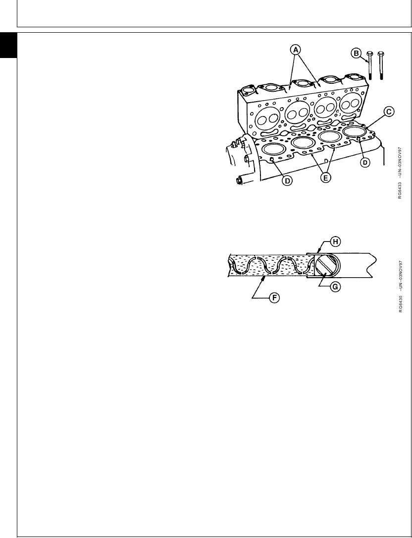
HEAD GASKET JOINT CONSTRUCTION AND
105
10
OPERATION
The head gasket joint consists of the following
components:
Cylinder
head gasket
Cylinder
head (A)
Cylinder
block (E)
Cylinder
liners (C)
Cylinder
head cap screws (B)
The head gasket must form an air-tight seal between
cylinder liners and cylinder head that can withstand the
temperatures and pressures of the combustion process.
The gasket must also form a liquid-tight seal between the
cylinder head and cylinder block to retain coolant and oil
in their respective passages. The gasket is constructed of
thin, formed sheets of steel-inserted, non-asbestos
material (F). The surface of gasket is treated to improve
liquid sealing and anti-stick characteristics. A fire ring
combustion seal (G) is located at each cylinder bore and
is held in place by a U-shaped stainless steel flange (H).
The cylinder head and block must be flat to provide an
even clamping pressure over the entire surface of gasket,
and must have the proper surface finish to keep gasket
material from moving in the joint. Dowels (D) are used to
properly locate head gasket on block.
The cylinder liners must protrude evenly from top of
cylinder block the specified amount to provide adequate
A--Cylinder Head
clamping force on fire ring of each cylinder.
B--Cylinder Head Cap Screws
C--Cylinder Liners
The cap screws must be proper length, made of proper
D--Dowel Pins
E--Cylinder Block
material, and be tightened to proper torque in order to
F--Gasket Body
provide an adequate clamp load between other joint
G--Fire Ring Combustion Seal
components.
H--Stainless Steel Flange
Each of the above components contributes to the integrity
of the head gasket joint. If any of these components do
not conform to specifications, gasket joint may fail
resulting in combustion leaks, coolant leaks, or oil leaks.
Continued on next page
RG,105,JW7658
1921NOV971/2
13-487