TM 5-3805-280-24-2
Fuel System Operation and Tests
115
39
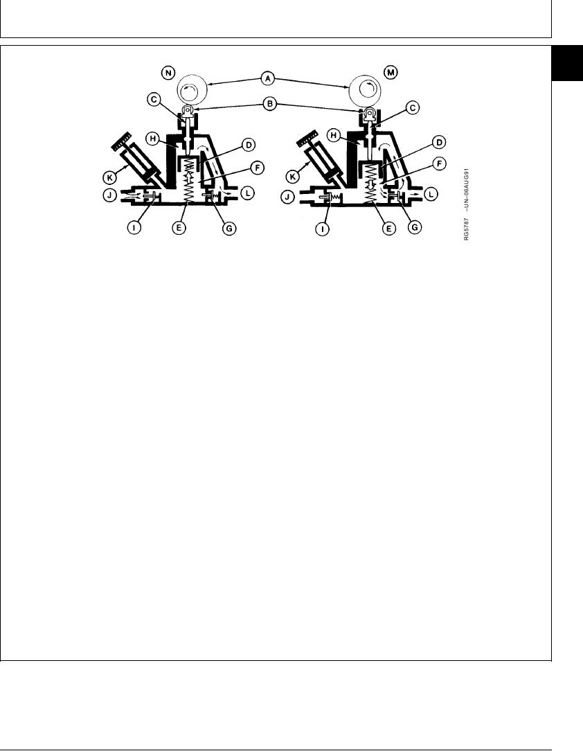
A--Camshaft
E--Plunger Spring
I--Suction Valve
M--Intermediate Stroke
B--Roller Tappet
F--Suction Chamber
J--Fuel Inlet
Position
C--Pressure Spindle
G--Pressure Valve
K--Hand Primer Pump
N--Suction and Discharge
D--Plunger
H--Pressure Chamber
L--Fuel Outlet
Stroke Position
injection pump. At the same time, plunger suction
As the pump camshaft (A) rotates toward the "high
pressure is permitting fuel to enter the suction
cam" intermediate stroke position (M), the roller tappet
chamber through the suction valve (I). With the suction
(B) and pressure spindle (C) cause the plunger (D) to
chamber charged with fuel, the pumping cycle begins
move against and compress the plunger spring (E).
again.
Plunger movement forces the fuel out of the suction
Fuel is allowed to flow in around the pressure spindle
chamber (F), through the pressure valve (G), and into
to lubricate the spindle as it moves back and forth in
the pressure chamber (H). The amount of fuel
housing. To prevent the fuel from entering the pump
discharged from the suction chamber is equal to the
crankcase, a rubber O-ring is positioned in the spindle
amount of fuel delivered for each stroke of the plunger.
bore of housing at the roller tappet end.
Towards the end of the intermediate stroke, the
spring-loaded pressure valve closes again.
Unscrewing the knurled knob on the hand primer pump
(K) and pulling upward causes the suction valve to
As the camshaft rotates toward the "low cam" or
open and fuel to flow into the suction chamber. When
suction and discharge position (N), plunger spring
the hand plunger is pushed downward, the suction
pressure causes the plunger, pressure spindle, and
valve closes, and fuel is forced out of the pressure
roller tappet to follow the camshaft.
valve.
Movement of the plunger pushes the fuel from the
pressure chamber, and delivers it to the fuel filters and
RG,115,JW7706 1924NOV972/2
13-566

