TM 5-3805-280-24-2
Fuel System Operation and Tests
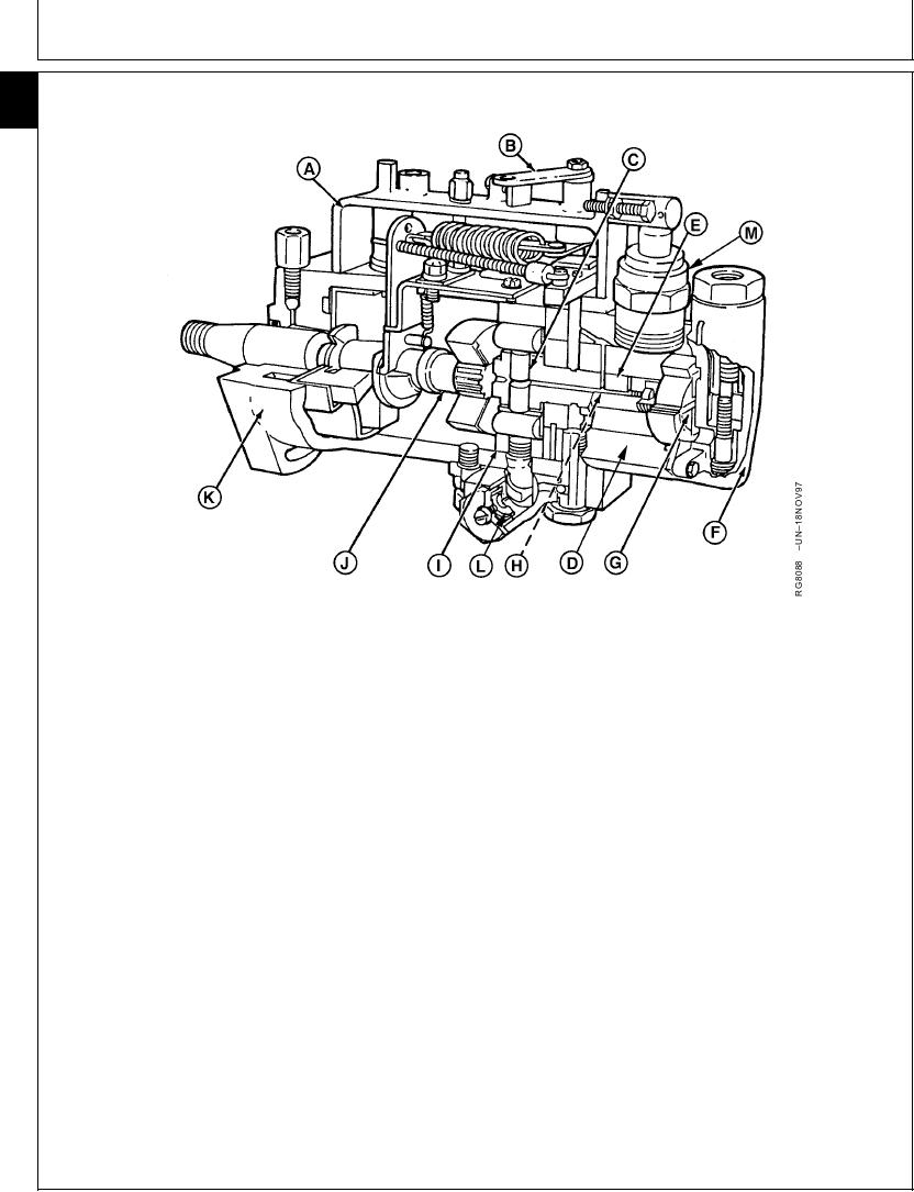
LUCAS ROTARY FUEL INJECTION PUMP OPERATION
115
62
A--Governor Housing
E--Distributor Rotor
I--Internal Cam Ring
M--Electric Shutoff
B--Throttle Lever
F--End Plate
J--Drive Shaft
C--Pumping Plungers
G--Supply Pump
K--Pump Housing
D--Hydraulic Head
H--Delivery Valve
L--Automatic Advance
As the rotor rotates, the inlet bore in pump head aligns
The Lucas fuel injection pump is a horizontally
with inlet bore in the rotor. Fuel coming from the
mounted distributor pump with mechanical governor
transfer pump reaches the pump plunger chamber's
and automatic hydraulic speed advance. The moving
through bore, regulated by the metering valve and
parts of the pump are simultaneously lubricated and
forces the two plungers apart.
cooled by diesel fuel flowing through the pump, no
additional lubricant is required.
During further rotation of the distributor rotor, inlet bore
in the pump head is closed and distributor channel in
Diesel fuel for injection is fed to the cylinders by a
the rotor eventually aligns with one of the outlet bores
single unit. The pumping plungers (C) and distributor
in the pump head. Meanwhile the two pump plungers
rotor (E) is fitted with two opposed plungers controlled
have reached the cam so that they move toward each
by an internal cam ring (I).
other. The trapped, metered fuel is forced, (under high
pressure) through a channel in the rotor and outlet
On the other end of the rotor, there is a supply pump
opening in the pump head. Then, through pressurizing
(G) which delivers the fuel, drawn from the fuel filter,
valve and pressure line, to the injection nozzle and into
through the metering valve into the inlet bore in the
the appropriate cylinder.
pump hydraulic head (D), at a pressure that varies with
engine speed.
Continued on next page
RG,115,JW7693
1924NOV971/2
13-589

