
TM 5-3805-280-24-2
Elements
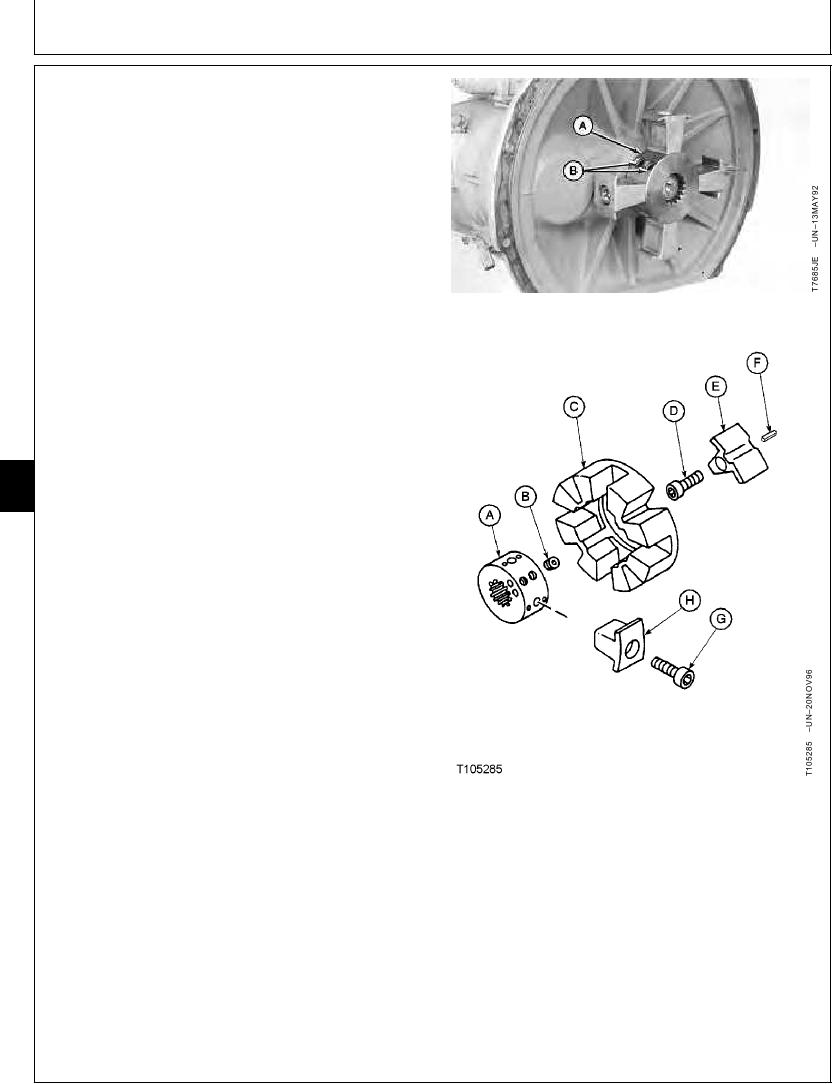
NOTE: Flex coupling may come off with pump or stay on
flywheel.
11. Remove parts (A--H).
12. Replace parts as necessary.
13. Install parts (A--H). Apply thread lock and sealer
(medium strength) to set screws (B) and to cap
screws (D and G).
14. Tighten set screws (B).
Coupling-to-Pump Shaft Set Screw--Specification
Torque ........................................................................... 108 Nm (80 lb-ft)
15. Tighten cap screws (D and G).
Insert-to-Flywheel Cap Screw--Specification
Torque ......................................................................... 215 Nm (160 lb-ft)
07
0752
Insert-to-Coupling Cap Screw--Specification
4
Torque ......................................................................... 215 Nm (160 lb-ft)
16. Install pump. Tighten cap screws.
Pump-to-Flywheel Housing Cap Screw--Specification
Torque ............................................................................. 49 Nm (36 lb-ft)
17. Connect hydraulic hoses and lines.
18. Connect wiring harnesses.
19. Install muffler and bracket.
20. Do Hydraulic Pump and Drive Gearbox Start-Up
Procedure. (See procedure in Group 3360.)
A--Coupling
B--Set Screw (2 used)
C--Flex Coupling
D--Cap Screw (4 used)
E--Insert (4 used)
F--Spring Pin (4 used)
G--Cap Screw (4 used)
H--Insert (4 used)
TX,07,UU3905
1919SEP983/3
15-4