
TM 5-3805-280-24-2
Frame Installation
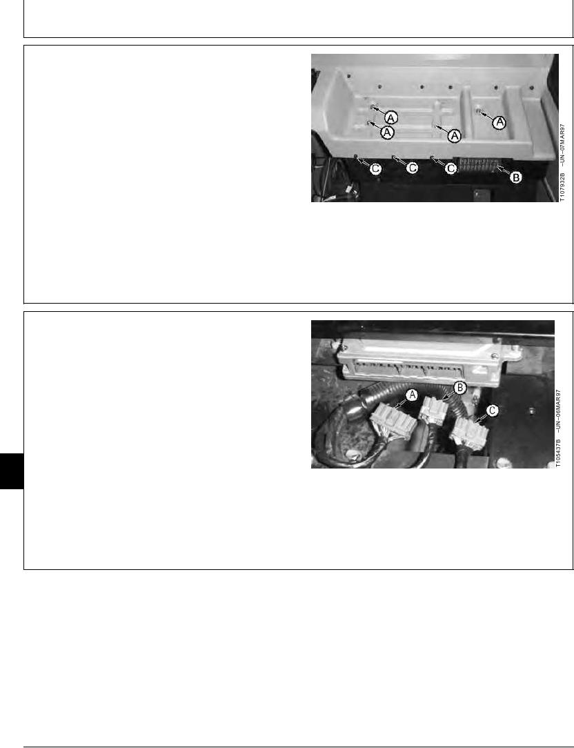
1. Disconnect the battery ground and positive cables.
2. Inside the cab, remove four cap screws (A and C) and
the fuse box cover (B) to remove the rear console
cover.
A--Cap Screws
B--Fuse Box Cover
C--Cap Screws
TX,16,UU3588
1919SEP982/3
3. Disconnect the engine and pump controller electrical
connectors.
4. After the welding on machine is completed, install the
connectors to the engine and pump controller and then
connect the battery cables.
5. Do Engine Speed Learning Procedure. (See procedure
in this group.)
17
1740
2
A--Connector
B--Connector
C--Connector
TX,16,UU3588
1919SEP983/3
17-2