
TM 5-3805-280-24-2
Hydraulic System
CAUTION: To avoid injury from escaping fluid
under pressure, stop engine, and relieve the
pressure in the system before disconnecting
hydraulic or other lines. Tighten all connections
before applying pressure.
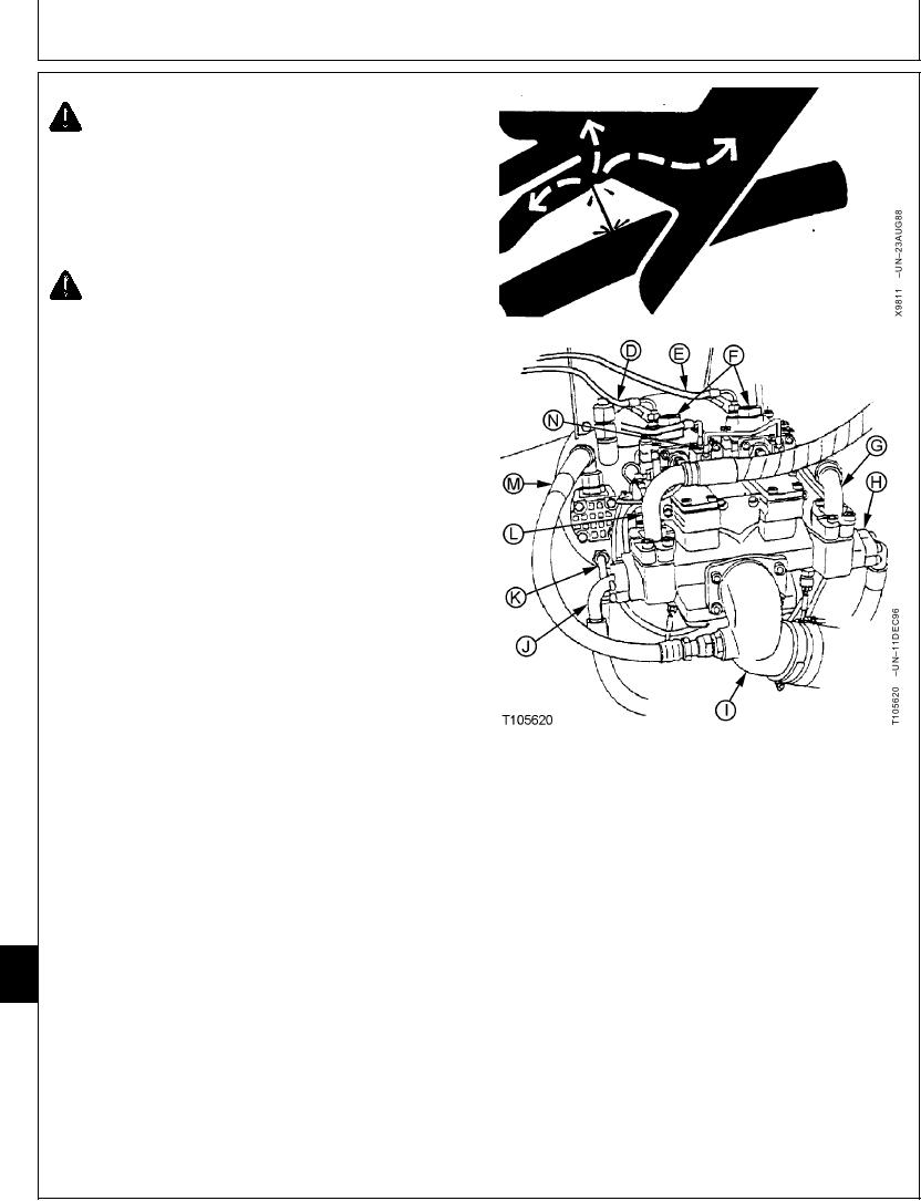
7. Disconnect lines (D, E and G--N).
CAUTION: The approximate weight of hydraulic
pump and drive gearbox is 170 kg (375 lb).
Hydraulic Pump and Drive Gearbox--Specification
Weight............................................................ 170 kg (375 lb) approximate
8. Install M12-1.75 metric lifting eyebolts, such as
JT05550 Metric Lifting Eyebolts, in tapped holes in air
bleed plugs (F) and pump drive gearbox housing.
Connect a hoist to eyebolts using lifting straps.
9. Remove pump drive gearbox-to-flywheel cap screw to
remove pump. Repair or replace pump.
10. Tighten pump drive gearbox-to-flywheel cap screw.
Pump Drive Gearbox-to-Flywheel Housing Cap Screw--
Specification
Torque ............................................................................. 49 Nm (36 lb-ft)
IMPORTANT: Hydraulic pump and drive gearbox will
be damaged if not filled with oil before
starting engine. Procedure must be
performed whenever a new pump or
D--Regulator-to-Rear Pump Control Valve Line
gearbox is installed or oil has been
E--Regulator-to-Front Pump Control Valve Line
F--Air Bleed Plugs
drained from the pump, gearbox or
G--Front Pump Outlet-to-Right Control Valve Line
hydraulic oil tank.
H--Attenuator Line
I--Inlet-to-Hydraulic Oil Tank Line
11. Fill pump housing and pump drive gearbox with oil.
J--Attenuator Line
(See Hydraulic Pump and Drive Gearbox Start-Up
K--Pilot Pump Outlet-to-Pilot Filter Line
L--Rear Pump Outlet-to-Left Control Valve
Procedure in this group.)
M--Pilot Pump Inlet Line
N--Regulator-to-Speed Sensing Solenoid Valve
Apply pipe sealant to drain plug threads.
Line
33
3360
22
Continued on next page
TX,33,UU3781
1921SEP983/4
21-64