
TM 5-3805-280-24-2
Hydraulic System
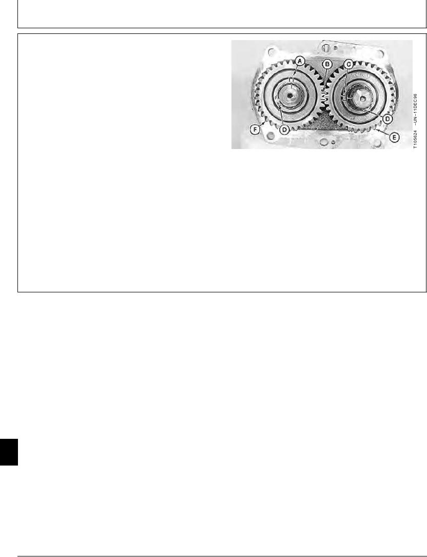
6. To aid assembly, make timing marks on drive gear (E),
drive shafts (A and C), and driven gear (14). The gears
are not interchangeable.
Measure the amount of backlash between gears.
Pump Drive and Driven Gear--Specification
Backlash ........................................................ 0.68 mm (0.027 in.) nominal
Backlash ................................................... 1.50 mm (0.059 in.) limit of use
Remove snap rings (16) to remove gears.
A--Front Pump Drive Shaft-to-Driven Gear Timing
Mark
B--Driven Gear-to-Drive Gear Timing Mark
C--Rear Pump Drive Shaft-to-Drive Gear Timing
Mark
D--Snap Ring (2 used)
E--Drive Gear
F--Driven Gear
Continued on next page
TX,33,UU3783
1921SEP986/17
33
3360
30
21-71