
TM 5-3805-280-24-2
Hydraulic System
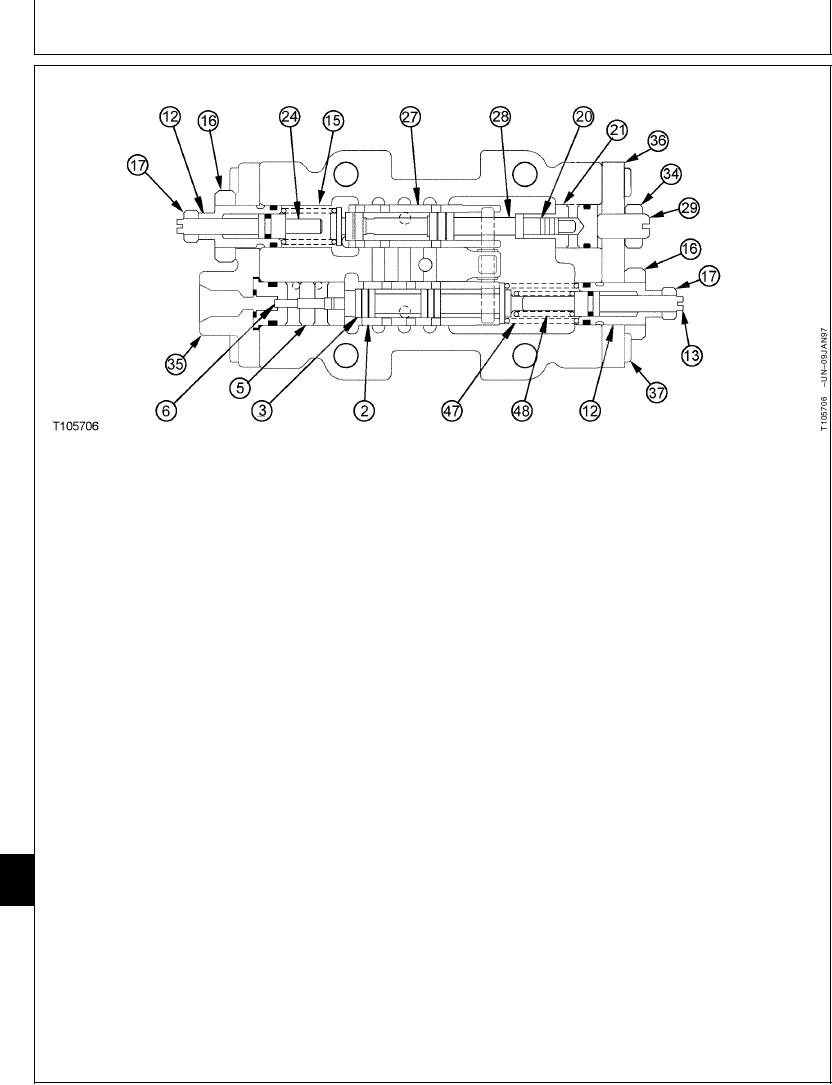
2--Load Sleeve
13--Load Adjusting Screw
27--Remote Control Sleeve
47--Outer Spring
3--Load Spool
(Stop)
28--Remote Control Spool
48--Inner Spring
5--Cylinder
16--Nut (2 used)
29--Minimum Flow
6--Load Piston
17--Nut (2 used)
Adjusting Screw
12--Load Adjusting
20--Piston
34--Nut
Cartridge (Stop)
21--Cylinder
35--End Plate
--Flow Adjusting
24--Maximum Flow
36--Cover
Cartridge (Stop)
Adjusting Screw (Stop)
37--Cap Screw (8 used)
8. Remove air bleed plugs from pump regulators.
IMPORTANT: Hydraulic pump will be damaged if
Install regulators making sure groove in remote
not filled with oil before starting
control sleeve (27) and load sleeve (2) engage
engine. Procedure must be
dowel pin in feedback link. Check through hole that
performed whenever a new pump
groove in sleeves engage dowel pin.
installed or oil has been drained
from the pump or hydraulic oil tank.
Tighten cap screws.
9. Fill pump housing with oil. (See Hydraulic Pump
Housing-to-Pump Housing Cap Screw--Specification
and Drive Gearbox Start-Up Procedure in this
group.)
Torque....................................................................... 49 Nm (36 lb-ft)
10. Check pump regulator adjustments. (See
Tighten the large air bleed plug (located on top of
Hydraulic Pump Regulator Test and Adjustments
regulator housing).
in Group 9025-25.)
Air Bleed Plug-to-Housing--Specification
33
3360
Torque....................................................................... 78 Nm (58 lb-ft)
52
TX,33,UU3785
1921SEP983/3
21-90