
TM 5-3805-280-24-2
Rock Drill
44
9506
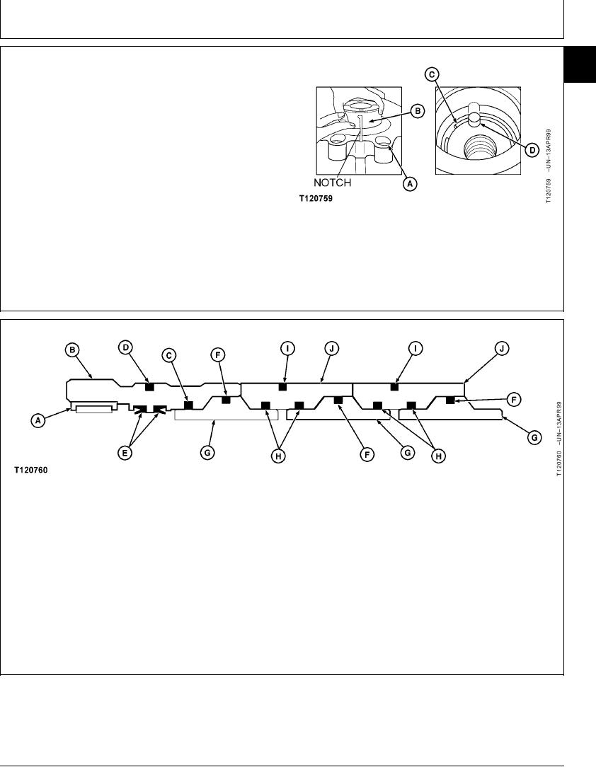
76. Mark the position of the internal notch of the thrust
67
housing (A).
77. Install hydraulic stop piston (B) with attached
components in thrust housing (A). Ensure that notch
is aligned with the mark.
78. Drive the hydraulic stop piston (B) with attached
components in the thrust housing (A) with a hydraulic
press.
79. Install snap ring (C) and pin (D).
A--Thrust Housing
B--Hydraulic Stop Piston
C--Snap Ring
D--Pin
CED,OUOE019,9 1912MAR9921/34
A--Needle Bearing
D--O-Ring
G--Tight Ring (3 used)
J--Tight Ring (2 used)
B--Tight Ring
E--Seal (2 used)
H--O-Ring (4 used)
C--O-Ring
F--O-Ring
I--O-Ring (2 used)
82. Install one new O-ring (F) in each of three tight
80. Using shouldered pin, 59828, install needle
rings (G).
bearing (A).
83. Install two new O-rings (H) and new O-ring (I) in
81. Install new O-rings (C and D) and two new seals
each of two tight rings (J).
(E) on tight ring (B).
Continued on next page
CED,OUOE019,9 1912MAR9922/34
23-63