
TM 5-3805-281-24-1
Sub-System Diagnostics
1 WORK AND DRIVE LIGHT CIRCUIT DIAGNOSTIC PROCEDURES
IMPORTANT: Do not disconnect electrical connectors while the engine is running. Damage to Engine and
Pump Controller or other components may result. Disconnect connectors only when instructed during a
test or check.
NOTE: Before troubleshooting the circuits, clean all terminals in the monitor controller and harness connectors
using a non-conductive lubricating contact cleaner, then try the circuit operation again before proceeding. TY16324
Contact Cleaner can be used.
1/1
Remove fuse block cover.
WORK AND DRIVE
YES: Fuse is OK.
LIGHTS 20 AMP FUSE
9015
(F11) CHECK
Remove fuse from fuse block.
NO: Replace Fuse. If
15
fuse blows again, check
34
Using ohmmeter, check fuse for continuity.
for short.
Is continuity measured?
1/1
YES: Relay is OK.
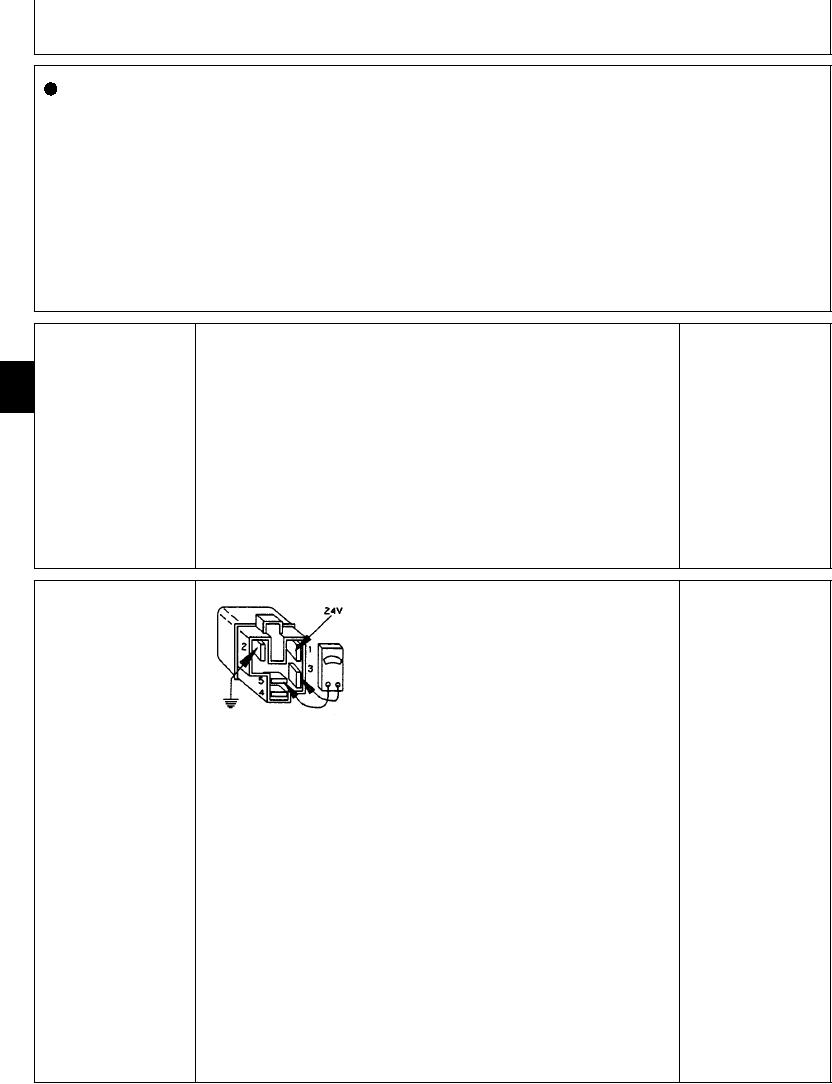
DRIVE LIGHT RELAY
1--24 Volt Terminal
(K4) CHECK
2--Ground Terminal
3--Relay Common
NO: Relay has failed.
4--Relay Normally Closed
Replace.
5--Relay Normally Open
Disconnect harness from relay.
Connect ohmmeter to terminals 3 and 5.
T7447BG
1914JAN91
Does ohmmeter read open?
Connect 24 volts to relay terminal 1 and ground terminal
2.
Does relay "click"?
With 24 volts still connected to terminal 1, connect
ohmmeter to terminals 3 and 5.
Does ohmmeter read continuity?
1/1