
TM 5-3805-281-24-1
Sub-System Diagnostics
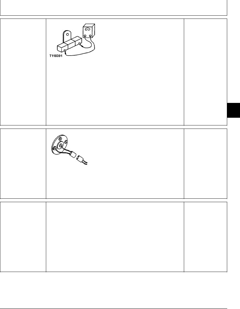
FUEL GAUGE RESISTOR
YES: Gauge has failed.
(R5) CHECK
Replace.
NO: Resistor has failed.
Replace.
T118391 UN21NOV98
NOTE: Check fuel gauge before checking resistor. Resistor is located on bottom of
monitor controller panel. Access resistor by removing bottom cover from monitor
controller panel.
Connect ohmmeter to resistor terminals.
Does ohmmeter read about 220 ohms?
9015
15
65
1/1
NOTE: Check fuel gauge before checking sensor.
FUEL LEVEL SENSOR
YES: Sensor has failed.
(B8) CHECK
Replace.
Disconnect harness from fuel level sensor.
NO: Check harness.
Observe fuel gauge.
Does gauge needle go to "E"?
Connect jumper wire between harness connector pins.
T7472AE UN11MAR91
Does gauge needle go to "F"?
1/1
FUEL LEVEL INDICATOR
With adequate fuel in tank, turn key switch ON.
YES: Indicator is OK. Go
LIGHT (H13) CHECK
to next check.
Observe fuel level indicator.
NO: If indicator does not
come ON, check indicator
Does indicator come ON when key switch is turned ON, then go OFF 2--3 seconds
lamp.
later?
If indicator does not go
OFF, go to next check.
1/1
4-133