
TM 5-3805-281-24-1
Sub-System Diagnostics
FUEL LEVEL SWITCH
Disconnect harness from fuel level switch.
YES: Fuel level switch
(B2) CHECK
has failed. Replace.
If indicator was ON, did it go OFF with harness
disconnected and key switch ON?
NO: Check harness.
If indicator was OFF, connect a jumper wire from
harness connector to ground.
Does indicator come ON when key switch is ON?
T7472AB
UN14MAR91
1/1
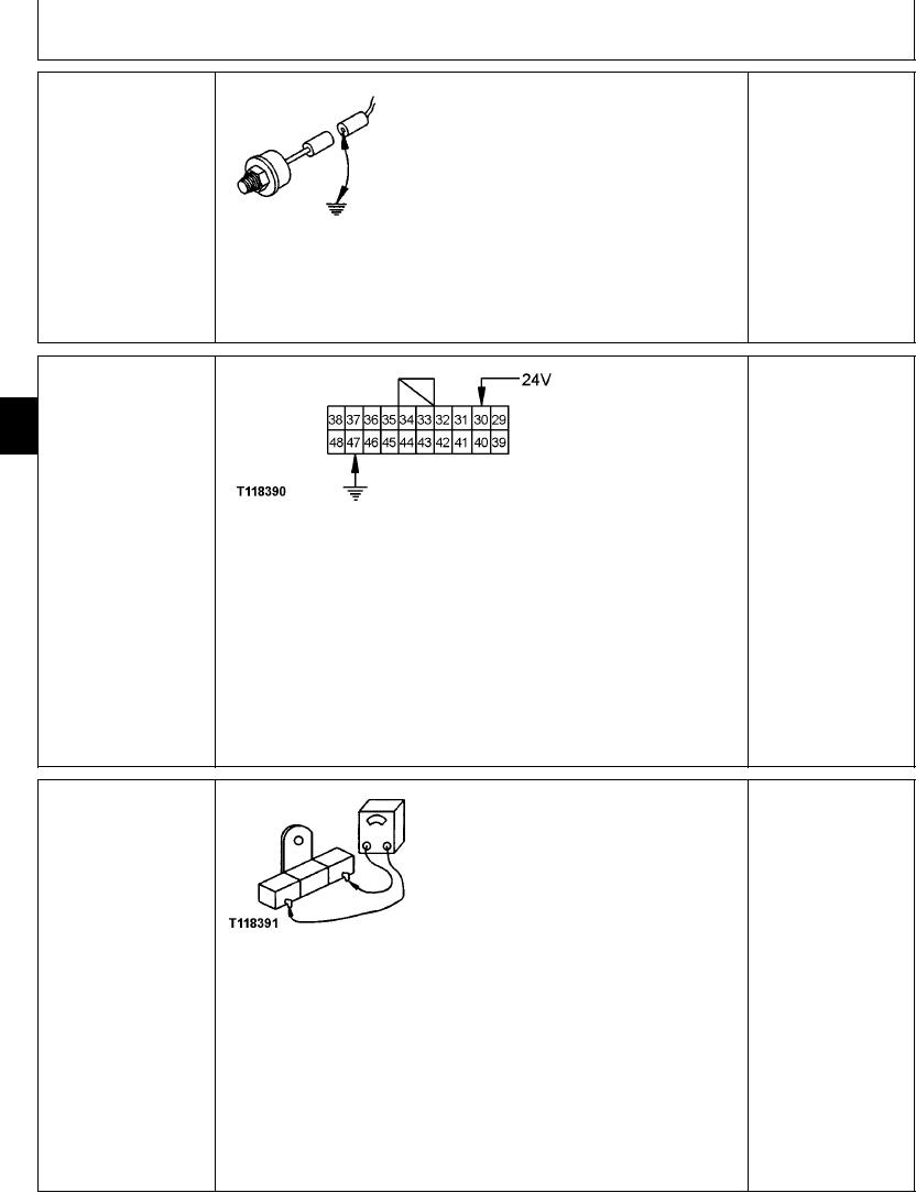
ENGINE COOLANT
YES: Gauge and gauge
TEMPERATURE GAUGE
resistor are OK. Go to
9015
(P2) CHECK
engine coolant
15
temperature sensor (B9)
66
check.
NO: Go to next check.
T118390 UN21NOV98
Disconnect 20-pin harness connector from monitor display and controller connector.
Connect 24 volts to 20-pin monitor display and controller pin 30.
Then ground pin 47.
Does gauge needle point to "C" with 24 volts applied to pin 30, and "H" with pin 47
grounded?
1/1
ENGINE COOLANT
YES: Gauge has failed.
TEMPERATURE GAUGE
Replace.
RESISTOR (R4) CHECK
NO: Gauge resistor has
failed. Replace.
T118391 UN21NOV98
NOTE: Check engine coolant temperature gauge before checking resistor. Resistor is
located on bottom of the monitor controller panel. Access resistor by removing bottom
cover from monitor controller panel.
Connect ohmmeter to resistor terminals.
Does ohmmeter read about 220 ohms?
1/1
4-134