
TM 5-3805-281-24-1
Diagnostic Information
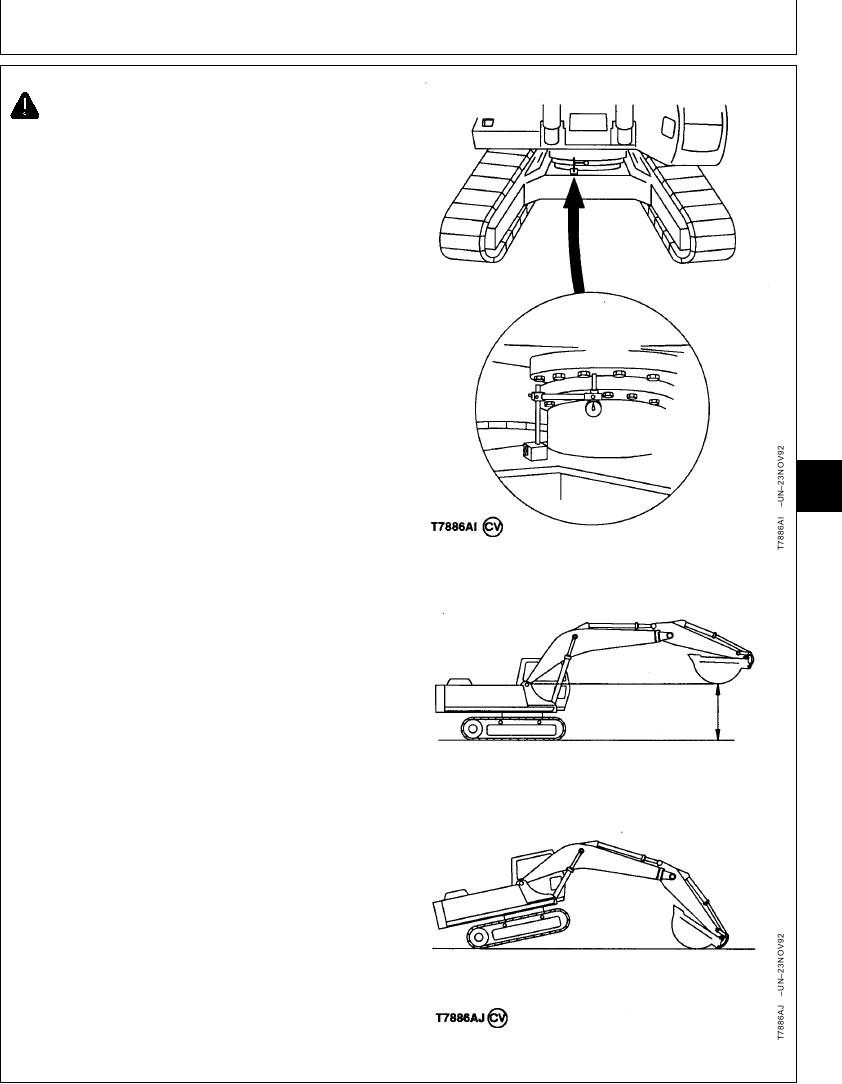
CAUTION: Stay clear of moving parts. Position
dial indicator so it can be seen while operator
can see you.
NOTE: Two people are needed to do the measurement.
One to operate the machine and one to take the
readings.
1. Check that swing bearing to main frame cap screws
are tight. (See Group 4350.)
Check that bearing is lubricated with the specified
grease. (See Track Adjuster, Working Tool Pivot,
Swing Bearing, and Swing Bearing Gear Grease in
General Information Section.)
Check that bearing rotation is smooth and without
noise.
2. Install the dial indicator with needle point contacting
bottom face of swing bearing outer race.
9020
15
3. Move boom and arm to position shown with bucket off
19
the ground.
4. Turn dial indicator to zero.
5. Lower boom to raise front idlers off the ground
approximately 500 mm (20 in.)
6. Record dial indicator reading.
If reading is more than maximum allowable, check for
steel ball and spacer wear. Repair or replace swing
bearing as needed. (See Group 4350.)
Swing Bearing--Specification
Play .......................................................... 1.4 mm (0.055 in.) or less new
Play............................................................... 4.7 mm (0.185 in.) maximum
used
CED,TX08227,3160
1930MAY982/2
5-22