
TM 5-3805-281-24-1
Adjustments
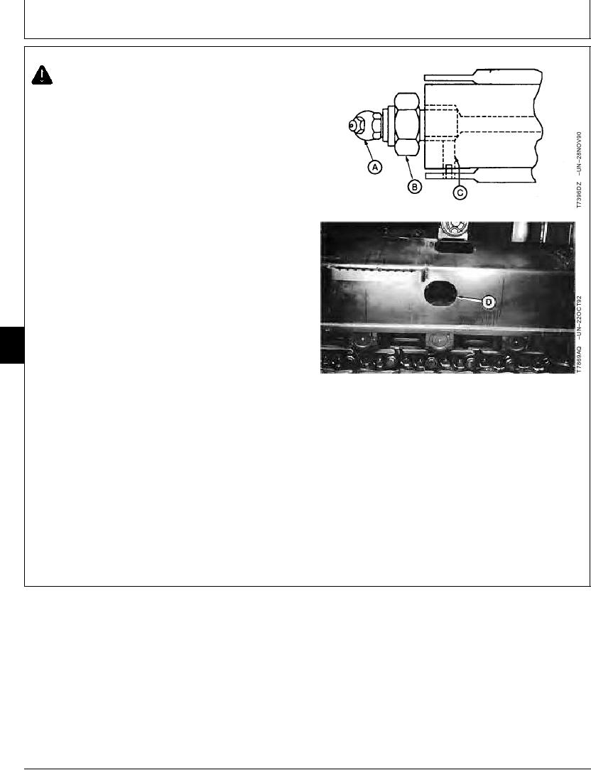
CAUTION: High pressure grease in track
adjuster cylinder. Do not remove grease fitting
or nut and valve assembly to release grease.
IMPORTANT: Prevent possible damage to track
components. Do not use the grease
fitting on track adjuster cylinder for
lubrication. Use this grease fitting only
for track sag adjustment.
5. To decrease track sag, add multi-purpose grease to
track adjuster cylinder through grease fitting (A) located
in access hole (D) in track frame. Use a grease gun
with a maximum capacity of 68 950 kPa (690 bar) (10
000 psi).
To increase track sag, loosen nut and valve assembly
(B) one turn to release grease from track adjuster
cylinder through bleed hole (C) in rod.
Tighten nut and valve assembly when track sag is
9020
correct.
20
2
Nut and Valve Assembly-to-Track Adjuster Cylinder--Specification
Torque ......................................................................... 147 Nm (108 lb-ft)
A--Grease Fitting
B--Nut and Valve Assembly
NOTE: If piston in track adjuster cylinder does not move,
C--Bleed Hole
remove the cylinder to make repairs. (See
D--Access Hole
Remove and Install Track Adjuster in Group
0130.)
CED,TX08227,3161
1930MAY983/3
5-24