
TM 5-3805-281-24-1
Group 20
Adjustment
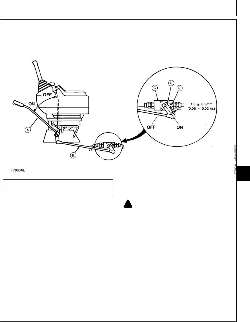
PILOT SHUT-OFF VALVE LINKAGE ADJUSTMENT
9025
20
1
SPECIFICATIONS
5. Pull pilot shut-off lever to the OFF position. Check
1.5 0.5 mm (0.06 0.02 in.)
that lever is against the rear stop.
Pilot Shut-Off Lever to Head of
Cap Screw Clearance
CAUTION: Machine may move if adjustment
1. Stop the engine.
is incorrect. Before checking pilot shut-off
lever adjustment, make sure the area around
2. Remove cover underneath operator's station.
machine is clear.
3. Push pilot shut-off lever (A) forward to the ON
6. Start the engine. Run engine at slow idle. Actuate
position. Check that lever is against the front stop.
the hydraulic functions. Hydraulic functions must not
move with the pilot shut-off lever in the OFF
4. Adjust ball joints on rod (B) to get the specified
position. If hydraulic function move, repeat
clearance between valve lever (D) and head of cap
adjustment procedure.
screw (E).
Pilot Shut-Off Lever to Head of Cap Screw--Specification
Clearance............................................. 1.5 0.5 mm (0.06 0.02 in.)
TX,9025,GG2108 1918NOV971/1