
TM 5-3805-281-24-1
Tests
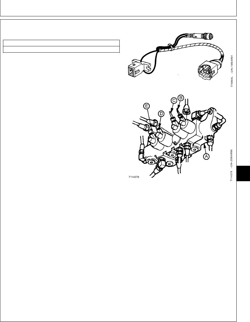
POWER BOOST SOLENOID VALVE (SG)
HARNESS TEST
ESSENTIAL TOOLS
JT07062 Test Harness
The purpose of test is to check continuity in the wiring
harness to the power boost solenoid valve (E) coil and
there is a signal from the engine and pump controller.
NOTE: Pressure reading shown on the laptop computer
for "Power boost control pressure" is a calculated
pressure from the electrical signal in the engine
and pump controller. A typical reading of 426 psi
is displayed when power boost switch on the right
control lever is pushed. A reading of 0 psi is
displayed when the switch is not pushed. The
readings indicates that the power boost switch is
OK and a electrical signal is generated. (For
circuit operation, see Power Boost Control Circuit
Operation in Group 9025-05.)
The power boost solenoid valve is also actuated
in Precision Work Mode when the boom up
function is actuated.
IMPORTANT: Turn key switch off before
9025
disconnecting any electrical
25
51
connectors. Disconnecting electrical
connectors while engine is running or
with key switch on can damage engine
A--Solenoid Valve Manifold
and pump controller or other electrical
B--Arm Regenerative Solenoid Valve (SC)
C--Speed Sensing Solenoid (SD)
components.
D--Propel Speed Change Solenoid (SI)
E--Power Boost Solenoid (SG)
1. Stop engine. Turn key switch to OFF.
2. Remove wire clip.
Wiggle connector half and pull apart; do not pull on
wiring leads.
3. Install test harness in series with wiring harness and
power boost solenoid valve (E).
4. Turn key switch to ON but do not start engine.
Continued on next page
CED,TX08227,3027 1918MAR981/2