TM 5-3805-281-24-1
Hydraulic System
1--Motor Valve Housing
10--O-Ring
19--Lip Seal
27--Piston Seal (2 used)
2--Bushing
11--Disk (4 used)
20--Center Shaft
28--O-Ring
3--Plate
12--Plate (5 used)
21--Motor Shaft and Brake
29--Servo Piston
4--Valve Plate
13--Spacer
Housing
30--Cover
5--O-Ring
14--Bearing
22--Pin
31--Socket Head Screws (4
6--O-Ring
15--Spacer
23--Piston (7 used)
used)
7--Disk Spring
16--Bearing
24--Rotor
8--Piston
17--Nut
25--Spring
9--O-Ring
18--Snap Ring
26--Link
02
0260
7
CED,OUOE023,172
1929MAY982/12
CAUTION: Use a lifting device for heavy
components.
IMPORTANT: Valve plate and pistons have machined
surfaces. Do not let valve plate and
pistons drop.
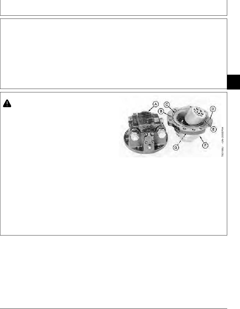
1. Remove four cap screws to remove propel motor valve
housing (A) from propel motor housing (F). Make sure
valve plate in valve housing is not damaged.
2. Remove parts (B--D and G).
A--Propel Motor Valve Housing
IMPORTANT: Pistons must be installed into the same
B--O-Ring
bores because of wear pattern. Mark
C--Disk Spring
D--O-Ring
pistons and respective rotor and shaft
E--Rotor Assembly
bores for assembly.
F--Propel Motor Shaft and Brake Housing
G--O-Ring
3. Mark pistons and bores in rotor (E) so pistons are
installed into the same bores at assembly. Remove
rotor assembly.
Continued on next page
CED,OUOE023,172
1929MAY983/12
10-46

