
TM 5-3805-281-24-1
Hydraulic System
Propel Motor and Brake-to-Frame Cap Screw--Specification
Torque ......................................................................... 265 Nm (195 lb-ft)
CED,OUOE023,168
1929MAY984/5
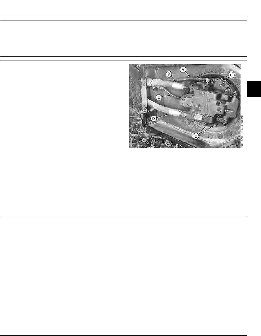
13. Connect lines (A--D).
14. Add gear oil. (See Swing Gearbox, Propel Gearbox,
02
and Pump Gearbox Oil, Group 0004.)
0260
3
15. Do propel motor start-up procedure. (See procedure
in this group.)
16. Install motor cover and tighten cap screws.
Propel Motor Cover Cap Screw--Specification
Torque ............................................................................. 90 Nm (65 lb-ft)
A--Motor Drain Port-to-Rotary Manifold Bottom
Tee Line
B--Port AV-to-Rotary Manifold Port 2 Line
C--Motor Speed Change Port-to-Rotary Manifold
Top Port Line
D--Port BV-to-Rotary Manifold Port 1 Line
E--Cap Screw and Lock Washer (6 used)
CED,OUOE023,168
1929MAY985/5
10-42