
TM 5-3805-281-24-2
Cylinder Head and Valves
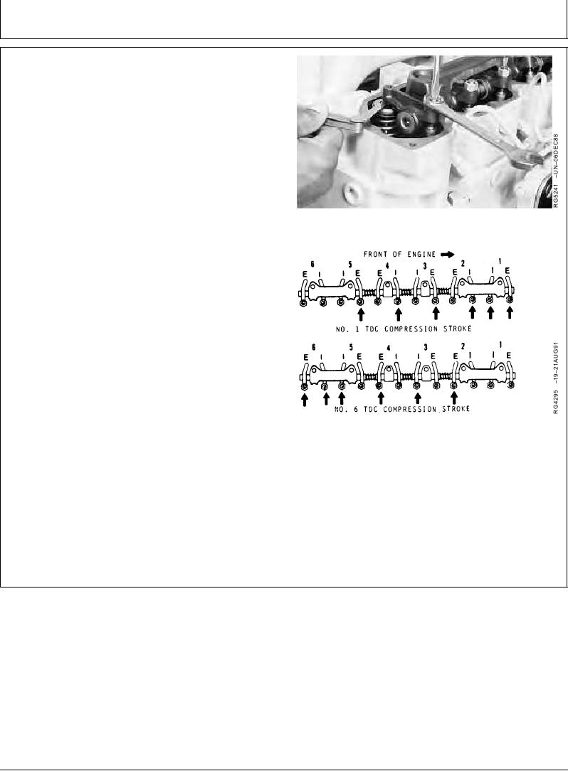
4. With engine lock-pinned at "TDC" of No. 1 piston's
compression stroke, check and adjust (as needed)
valve clearance on Nos. 1, 3, and 5 exhaust valves
and Nos. 1, 2, and 4 intake valves.
Intake Valve--Specification
Clearance ................................................. 0.46 0.05 mm (0.018 0.002
in.)
Exhaust Valve--Specification
Clearance ................................................. 0.71 0.05 mm (0.028 0.002
in.)
Adjusting Valve Clearance
5. If valve clearance needs to be adjusted, loosen the
lock nut on rocker arm adjusting screw. Turn adjusting
screw until feeler gauge slips with a slight drag. Hold
the adjusting screw from turning with screwdriver and
tighten lock nut to 27 Nm (20 lb-ft). Recheck
clearance again after tightening lock nut. Readjust
clearance as necessary.
6. Rotate flywheel 360 until No. 6 piston is at "TDC" of
its compression stroke. Rocker arms for No. 6 piston
should be loose.
7. Check and adjust (as needed) valve clearance to the
same specifications on Nos. 2, 4, and 6 exhaust and
Nos. 3, 5, and 6 intake valves. Tighten valve adjusting
Valve Adjusting Sequence
screw lock nut to 27 Nm (20 lb-ft).
8. Recheck clearance on all valves again after lock nut is
tightened.
RG,RG34710,1069
1923OCT972/2
11-93