
TM 5-3805-281-24-2
Cylinder Head and Valves
CHECK VALVE LIFT
IMPORTANT: For a more accurate measurement, it is
recommended that valve lift be
measured at 0.00 mm (in.) valve
clearance and with engine COLD.
NOTE: Measuring valve lift can give an indication of wear
on camshaft lobes and cam followers or wear on
camshaft lobes and cam followers or bent push
rods.
1. Remove turbocharger oil inlet clamp and rocker arm
cover. Loosen lock nut on rocker arm. Set valve
clearance at 0.00 mm (in.) on valve being checked.
Tighten lock nut.
2. Put dial indicator tip on valve rotator. Be sure that
valve is fully closed.
3. Check pre-set on dial indicator. Set dial indicator
pointer at zero.
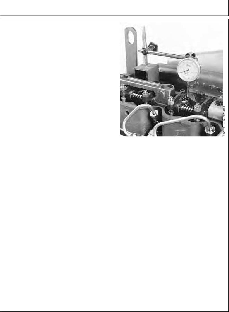
Checking Valve Lift
4. Manually turn engine in running direction, using the
engine rotation tools previously mentioned for checking
valve clearance.
5. Observe dial indicator reading as valve is moved to
fully open position. Record reading and valve number.
Intake Valve--Specification
Lift .......................................................... 13.53--13.71 mm (0.533--0.540
in.) at 0.00 mm (in.) clearance
Wear Tolerance ..................................... 12.65 mm (0.498 in.) at 0.00 mm
(in.) clearance
Exhaust Valve--Specification
Lift .......................................................... 14.52--14.60 mm (0.572--0.579
in.) at 0.00 mm (in.) clearance
Wear Tolerance ..................................... 13.64 mm (0.537 in.) at 0.00 mm
(in.) clearance
6. Reset valve clearance to specification after measuring
lift. (See CHECK AND ADJUST VALVE CLEARANCE,
earlier in this group.)
7. Repeat procedure on all remaining valves.
RG,RG34710,1070
1923OCT971/1