
TM 5-3805-281-24-2
Camshaft and Timing Gear Train
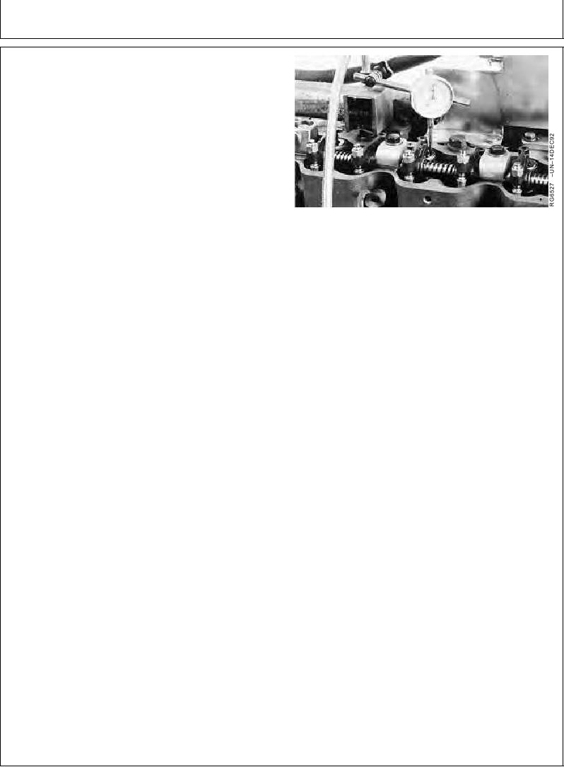
CHECK VALVE LIFT
IMPORTANT: For a more accurate measurement,
measure valve lift at 0.00 mm (in.)
rocker arm-to-valve tip clearance.
NOTE: Measuring valve lift provides an indication of wear
on camshaft lobes and cam followers or bent
push rods.
1. Remove rocker arm cover. Loosen locknut on rocker
arm and set valve clearance at 0.0 mm (in.). Tighten
Checking Valve Lift
locknut.
2. Put dial indicator tip on valve rotator. Be sure that
valve is fully closed.
3. Check pre-set on dial indicator. Set dial indicator
pointer at zero.
4. Manually turn engine in running direction, using the
engine rotation tool previously mentioned for checking
valve clearance.
5. Observe dial indicator reading as valve is moved to
fully open position. Valve lift must be no less than
limits shown.
Intake Valve--Specification
Lift .......................................................... 13.53--13.71 mm (0.533--0.540
in.) at 0.00 mm (in.) clearance
Wear Limit ............................................. 12.65 mm (0.498 in.) at 0.00 mm
(in.) clearance
Exhaust Valve--Specification
Lift .......................................................... 14.52--14.70 mm (0.572--0.579
in.) at 0.00 mm (in.) clearance
Wear Limit ............................................. 13.64 mm (0.537 in.) at 0.00 mm
(in.) clearance
6. Follow same procedure for all remaining valves and
adjust valve clearance to specification. (See CHECK
AND ADJUST VALVE CLEARANCE in Group 05.)
RG,RG34710,1198
1923OCT971/1