TM 5-3805-281-24-2
Removal and Installation
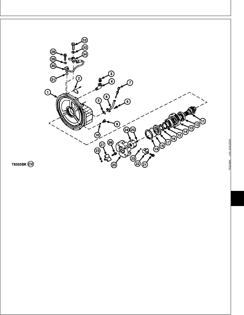
ASSEMBLE SPLITTER HOUSING
1--Housing
10--Packing
19--Snap Ring
28--Cap Screw
2--Screw (2 used)
11--Shaft
20--Set Screw (2 used)
29--Washer
3--Plug
12--Ball Bearing
21--Cap Screw (4 used)
30--Engine Speed Sensor
4--Elbow Fitting
13--Drive Gear
22--Insert (4 used)
(N Sensor)
08
5--Gasket
14--Ball Bearing
23--Spring Pin (12 used)
31--O-Ring
0800
6--Oil Tube
15--Snap Ring
24--Coupling
32--Cap Screw
9
7--Dipstick
16--Oil Seal
25--Flex Coupling
33--Lock Washer
8--Cap Screw (2 used)
17--Cover
26--Cap Screw (4 used)
34--Connector Bracket
9--Plug
18--O-Ring
27--Insert (4 used)
3. Install gasket (5), oil tube (6), dipstick (7), and cap
1. Starting with ball bearing (12), install parts (11--19)
screws (8).
in housing (1).
4. Install parts (28--34). Tighten cap screw (28).
Ball bearings (12 and 14) are a press fit in housing
and on drive shaft (11).
Speed Sensor Cap Screw--Specification
Install oil seal (16) in cover (17) so lip (spring side)
Torque..................................................................... 9.8 Nm (87 lb-in.)
is toward ball bearing (14).
2. Clean threads of elbow fitting (4) and plug (3) using
clean and cure primer. Apply pipe sealant to
threads. Install fitting and plugs.
Continued on next page
CED,OUOE024,233
1922MAY981/3

