
TM 5-3805-281-24-2
Hydraulic System
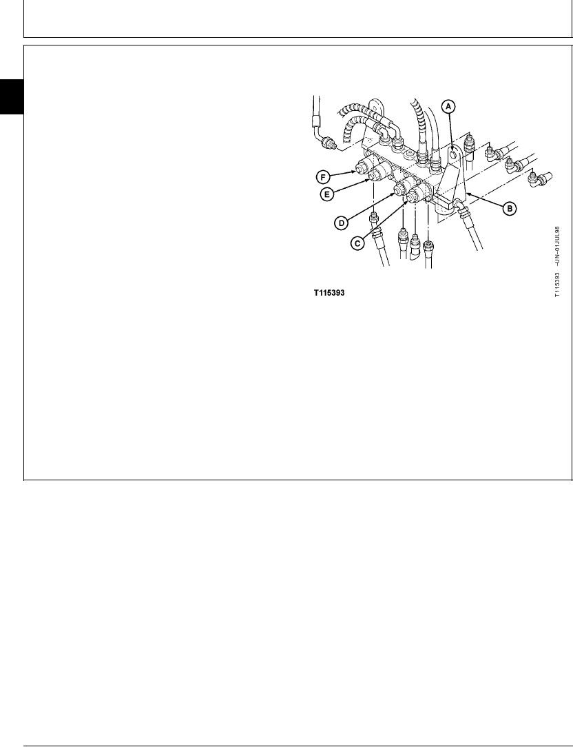
3. Disconnect wiring harness connectors at each solenoid
valve (C--F).
33
3360
4. Remove cap screws (A) to remove solenoid valve
66
manifold block (B). Repair or replace part as
necessary.
5. Install solenoid valve manifold (B) using two cap
screws (A). Tighten cap screws.
Solenoid Valve Manifold-to-Control Valve Mounting Bracket Cap
Screw--Specification
Torque ............................................................................. 20 Nm (16 lb-ft)
6. Connect wiring harness connectors.
7. Connect lines.
8. Check pressure setting of proportional solenoid valves.
(See Proportional Solenoid Valve Test and Adjustment
in Group 9025-25.)
A--Cap Screw (2 used)
B--Solenoid Valve Manifold
C--Arm Regenerative Solenoid Valve (BLU/WHT
and BLU/ORN Wiring Leads)
D--Speed Sensing Solenoid Valve (RED/WHT and
RED/YEL Wiring Leads)
E--Propel Speed Change Solenoid Valve
(LGRN/RED and LGRN/BLK Wiring Leads)
F--Power Boost Solenoid Valve (BLK/RED and
BLK/BLU Wiring Leads)
CED,OUOE026,55
1926JUN984/4
19-102