TM 5-3805-281-24-2
Hydraulic System
A--Plug (2 used)
E--Ball (4 used)
H--O-Ring (4 used)
L--Ring
B--Plug (2 used)
F--Flow Regulator Valve
I--Plug (2 used)
M--Orifice
C--O-Ring (2 used)
Housing
J--Spring (2 used)
N--Orifice
33
D--Spring (2 used)
G--Ball (4 used)
K--Spool
3360
89
IMPORTANT: The size of orifice (M) in spool (K) is
2. Check seats in housing for check valve balls (E).
unique to this machine. Spool with
Tighten plug (B).
the correct orifice must be used for
Check Valve Ball-to-Housing Plug--Specification
proper operation.
Torque...................................................................... 10 Nm (86 lb-in.)
1. Check that spool (K) slides smoothly in bore. Check
that orifice (M) in spool is clean.
3. Check that orifice (N) is clean. Tighten orifice.
Tighten plugs (A and I).
Orifice-to-Housing--Specification
Spool-to-Housing Plug--Specification
Torque...................................................................... 10 Nm (86 lb-in.)
Torque....................................................................... 49 Nm (36 lb-ft)
CED,OUOE027,270
1929MAY982/2
REMOVE AND INSTALL CONTROL VALVE
CAUTION: The hydraulic oil tank is pressurized.
High pressure release of oil from pressurized
system can cause serious burns or penetrating
injury. Release pressure from tank by loosening
vent plug. It is not necessary to remove vent
plug.
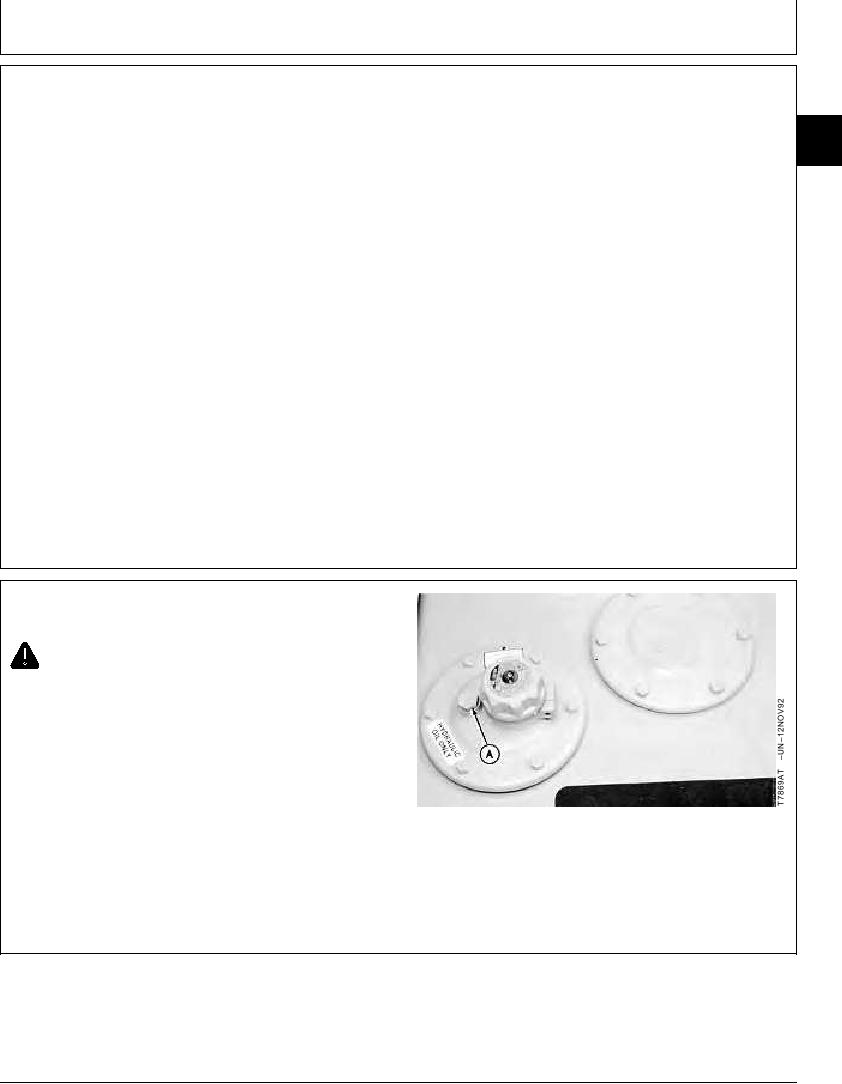
1. Loosen vent plug (A) to release air pressure from
hydraulic oil tank.
2. Pull a vacuum in hydraulic oil tank using a vacuum
A--Vent Plug
pump or drain hydraulic oil tank. Approximate oil
capacity is 159 L (42 gal).
Continued on next page
TX,33,GG2561 1912MAR971/9

