
TM 5-3805-281-24-2
Hydraulic System
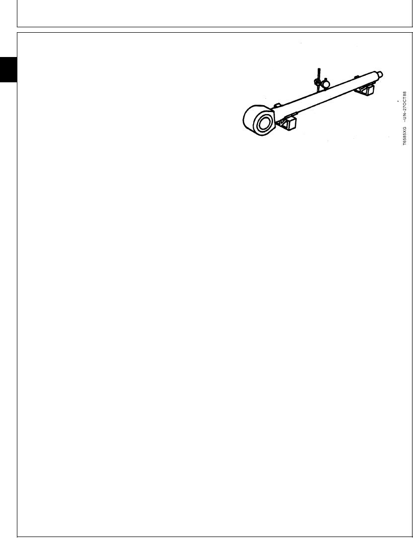
18. Check for rod curvature.
33
Put rod on V-blocks. Measure for rod curvature using
3360
a dial indicator.
176
19. Inspect rod surface for scratches or wear.
Boom Rod--Specification
Curvature ................................................... 0.5 mm per 1 m (0.020 in. per
3.25 ft)
Boom Rod Allowable Scratch--Specification
Depth .......................................................... 0.1 mm (0.004 in.) (enough to
detect by a fingernail)
Boom Rod--Specification
OD .................................................................... 105.0 + 0.036 - 0.090 mm
(4.1339 + 0.0014 - 0.0035 in.)
Arm Rod--Specification
Curvature ................................................... 0.5 mm per 1 m (0.020 in. per
3.25 ft)
Arm Rod Allowable Scratch--Specification
Depth .......................................................... 0.1 mm (0.004 in.) (enough to
detect by a fingernail)
Arm Rod--Specification
OD .................................................................... 115.0 + 0.036 - 0.090 mm
(4.5276 + 0.0014 - 0.0035 in.)
Bucket Rod--Specification
Curvature ................................................... 0.5 mm per 1 m (0.020 in. per
3.25 ft)
Bucket Rod Allowable Scratch--Specification
Depth .......................................................... 0.1 mm (0.004 in.) (enough to
detect by a fingernail)
Bucket Rod--Specification
OD ......................................................... 95.0 + 0.036 - 0.090 mm (3.7402
+ 0.0014 - 0.0035 in.)
CED,OUOE026,4
1918JUN9818/18
19-203