
TM 5-2420-230-24-1
Maintenance & Service Manual
R & HR32000 3 & 6 Speed LD
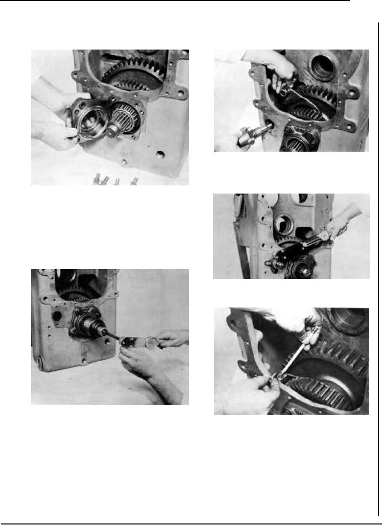
Figure 11
Locate high-low range shift fork in shift hub with offset of fork
toward gear. Insert rail support and rail into bore in transmission
housing and into shift fork.
Figure 9
Using new "O" rings install rear output bearing cap and taper
bearing cup on transmission case. Lube opening in bearing cap
must be aligned with lube opening in case. Tighten bearing cap
bolts to specified torque. (See torque chart.)
Install front bearing cap and shims. Tighten bolts to specified
Loosen front bearing cap bolts.
Figure 12
Tighten support bolts to specified torque. (See torque chart).
Figure 10
Using a inch lb. torque wrench, determine the rolling torque of
Figure 13
the output shaft and record. Tighten front bearing cap bolts to
Locate lockscrew hole in shift rail with hole in shift fork. Install
specified torque. Check rolling torque with bolts tight. Torque
lockscrew, tighten securely and lockwire to prevent loosening.
must be 8 to 8 inch lbs. [0.68 - 0.90 N.m] more than when bear-
ing cap bolts were loose. Add or omit shims on the front bearing
Proceed with Figure 228 in the R & HR 32000 3-Speed Section.
cap to achieve the proper preload.
--87--
F-132