
TM 5-2420-230-24-2
Accessories - Removal (0-36)
Section 0 - Engine Disassembly and Assembly - Group 00
Page 0-24
B Series Shop Manual
Accessories - Removal (0-36)
10 mm, 14 mm, 18 mm
If equipped, remove all additional gear driven accesso-
ries, (air compressor, hydraulic pump, etc.).
NOTE: Refer to the Manufacturer's Service Information for
repair instructions.
Injection Pump - Removal (Rotary Type
Pumps) (0-37)
13 mm
Caution: A diesel engine cannot tolerate dirt or water in
the fuel system. A tiny piece of dirt or a few drops of
water in the injection system can cause damage to the
system.
Clean all external surfaces of the injection pump, includ-
ing all line connections and fittings that are to be discon-
nected. Clean the area around the injection pump gear
cover to prevent dirt from entering the crankcase.
Remove the injection pump support bracket and
capscrews.
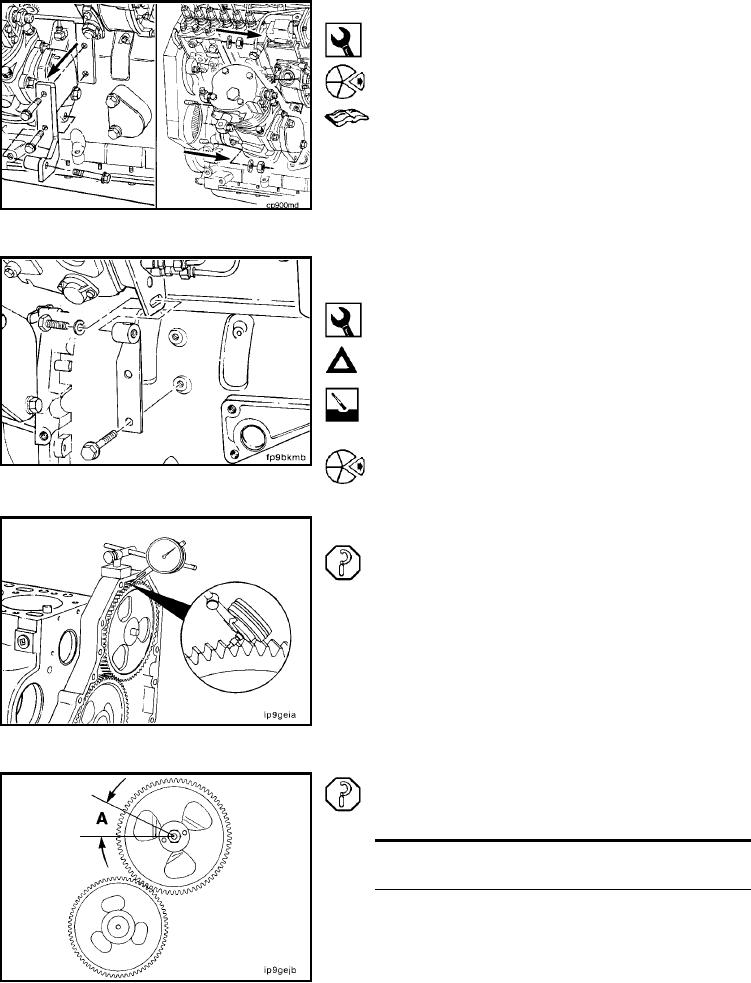
Gear Lash - Check (0-38)
Position an indicator on the tooth of the injection pump
drive gear.
Note the total indicator travel as injection pump drive gear
backlash. Mark the pump drive gear and camshaft gear
for further analysis if the backlash exceeds the limits.
Injection Pump Drive Gear
Backlash Limit (A)
mm
in
0.076
MIN
0.003
0.330
MAX
0.013
NOTE: Prevent movement of adjoining gear when checking
backlash or the reading will be the total of both gears.
L-113