
TM 5-2420-230-24-2
Section 14 - Engine Testing - Group 14
General Engine Test Procedures - (Chassis Dynamometer) (14-05)
B Series Shop Manual
Page 14-23
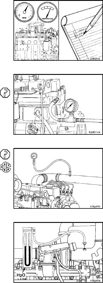
To correctly monitor an engine's performance, record the
following parameters:
Lubricating oil pressure (vehicle instrument panel)
Coolant temperature (vehicle instrument panel)
Coolant pressure
Turbocharger outlet pressure
Exhaust restriction
Intake manifold pressure
Inlet air restriction
Blowby
Engine speed (RPM) (vehicle instrument panel)
Wheel horsepower (WHP) (dynamometer controls)
Measure the coolant pressure at the cylinder head, rear
fuel pump side.
Minimum Gauge Capacity:
415 kPa [60 psi]
Measure turbocharger outlet pressure and intake mani-
fold pressure. The drop in pressure accross the
aftercooler/charge air cooler must not exceed 21 kPa [3
psi].
Connect a water manometer to the turbocharger air inlet
pipe to test air restriction.
NOTE: The manometer connection must be installed at a 90
degree angle to the air flow in a straight section of pipe, one
pipe diameter before the turbocharger.
NOTE: A vacuum gauge can be used in place of the water
manometer.
Minimum Gauge Capacity:
760 mm H20 [30 in. H20]
L-453